Nomic – no FSK? No way! by Erik, K5WW
I thought of this simple little modification for the Rigblaster Nomic one day, after getting tired of the constant fiddling with the soundcard volume to keep the ALC under control whenever I switched between AFSK in MMTTY and PSK31 in DigiPan.
At the time I was using a Kenwood TS-570S(G), which is equipped with an FSK connection on the back, and I knew that true FSK for RTTY would be better, in order to generate a cleaner and stronger signal, and to make use of the FSK filters in the radio.
The little circuit that I added can be found almost everywhere amateur radio programs for the soundcard are mentioned. A good place to find this circuit is at Don AA5AU’s website. On that site you will find everything from setting up MMTTY to fixing RFI problems. The actual switching diagram can be found on page 5. I used a 2N4401 NPN switching transistor, available from Radio Shack (Cat. No. 276-2058)
I wanted a clean solution that would fit in one box, and that would not take up another serial port, as I had run out of those too many times already. The following is a short overview of how I accomplished that, accompanied by some photos.
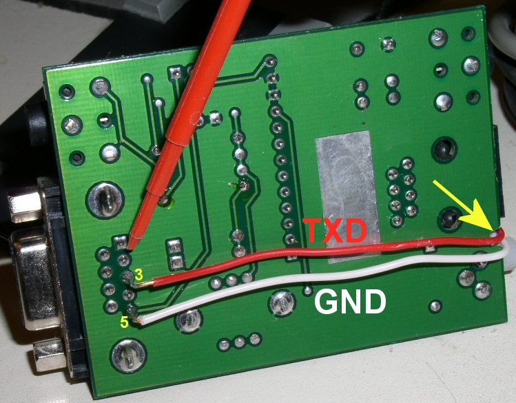
First of all I soldered two wires to the bottom of the serial cable receptacle. One goes to pin 3 (TXD) and connects to the base of the transistor; the other one is connected to pin 5 (ground) and connects to the transistor’s emitter.
I didn’t want to drill a hole in the PCB to bring the leads to the other side (where there’s more room to fit the switching circuit) so I filed off some PCB material at an unused spot on the side. The wires will then fit nicely between the PCB and the enclosure.
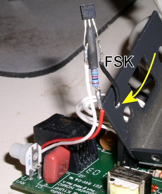
Here’s the FSK switching circuit in all its glory. Nothing to it, as you can see. (Actually, talking about it takes longer than making it!)
The black lead goes to the radio’s FSK connection. There weren’t many options to bring this wire out of the enclosure (West Mountain Radio makes good enclosures!) so I decided to drill a tiny little hole right above the output level pot.
Amazing how detailed these pictures are; you can see what a crummy soldering job I did 🙂
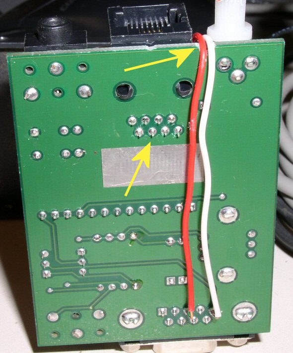
The bottom of the PCB again from another angle. On top you can see the little notch I filed into it, so the wires fit snugly and stay in place.
A tip for those that use their Nomic with only one radio: instead of using a separate wire for FSK to the radio you can hook that lead up to the receptacle of the RJ-45 connector. If you do that you will have only one cable (with PTT, FSK and audio wires) going to the radio. No need to drill a hole, it looks a little neater and is stronger. And you’ll have less “spaghetti” behind the radio!
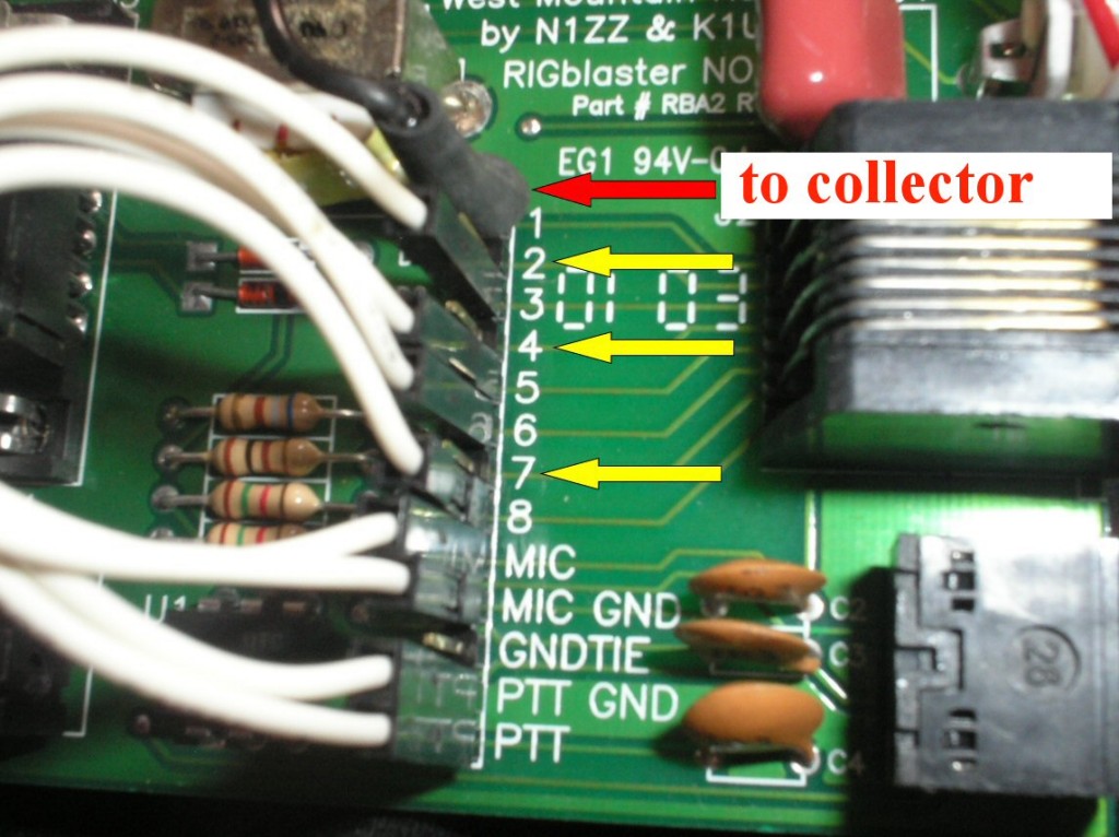
Find an unused pin (second arrow) on the RJ-45 connector and solder the collector side of the transistor to it. Or you could use one of the jumper pins on the component side of the PCB (it’s a little more convenient to solder and will be stronger), see last picture.
In this case I soldered the wire going to the collector to pin 1 of the RJ-45 connector (the red arrow). But as you can see there were 3 other pins (yellow arrows) that were unused. I just used pin 1 because it was easier to get to…
Happy diddling! 73,
K5WW