In early November 2015, the shaft supporting the two reels of copper beryllium tape broke inside the Director EHU (element housing unit) for my 3-element SteppIR (originally installed 2012 – referred to here as the 2012 EHU). I troubleshot the problem for a week before finally finding the broken reel shaft in the Director EHU. The troubleshooting page can be found here.
Luck would have it that I already had parts to repair the 2012 EHU. During Hurricane Isaac in August 2012, one of the ESTs (element support tubes) was ripped away from the EHU (see photo A) on my first-ever 3-element SteppIR (originally installed 2010 – referred to here as the 2010 EHU). However, the entire inside motor assembly was in excellent condition and the copper tapes were not damaged.
In order to get back on the air as quickly as possible, I decided to take the motor assembly out of the 2010 EHU and put it into the 2012 EHU shell. I was in the middle of working the WAEDC RTTY contest on Saturday when I decided to make the repair. So I quit the contest and started working on the EHU.
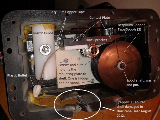
I removed the motor assembly from the 2010 EHU by first removing the plastic bullets from the ends of the copper tapes and spooling the tapes back out of the plastic guide up to the contact plate. I removed the plastic guide and put the plastic bullets temporarily back onto the ends of the copper tapes so the tapes would not slip back into the contact plate (the tape reels are spring loaded to keep tension on the tapes). I then removed the three screws holding the mounting plate and pulled the motor assembly out of the damaged shell. (For better photos on disassembling older EHUs, check out this excellent PDF created by Pedro, EA1YO, here and also this page by Randy, W5UE, here.). I then loosened the CGB fitting for the control cable and pulled the cable out of the CGB.
I then removed the motor assembly from the 2012 EHU with the broken reel shaft using a similar procedure as the 2010 EHU except the 2012 EHU has the EST in place. I first removed the bullets from the ends of the tapes and then removed all the jumbled tape. I then removed the 3 screws holding the mounting plate to the outer shell. This is when the spools fell out and exposed the broken reel shaft.
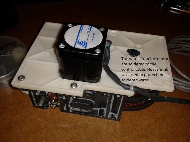
The control cable for the older style EHU comes into the EHU though a plastic CGB-type through-wall fitting. The wires for the control cable are soldered directly to the motor wires and it’s all nicely protected by heat shrink as shown in Photo D.
Newer EHUs do not use the CGB method of bringing the control cable into the EHU. Instead, the cable is placed in a recessed channel in the EHU outer shell. The cable is then terminated into a 4-prong connector that connects to a circuit board attached to the mounting plate inside the EHU. In order to accommodate the control cable wiring in the newer EHU shell, I needed to terminate the motor wiring to the circuit board instead of having it soldered to the control cable.
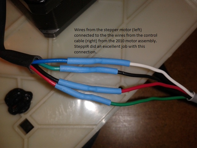
I removed the outer-most heat shrink. This exposed the point where the motor wires are connected to the control cable wires. I was happy to see SteppIR did a nice job with this.
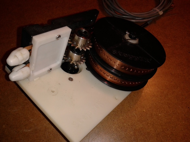
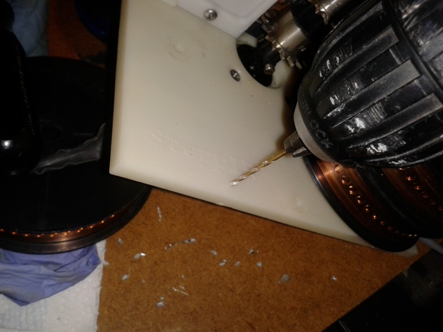
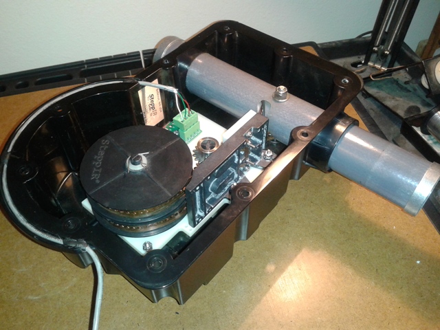
I removed the circuit board from the 2012 motor assembly and installed it in the same location on the plastic mounting plate for the 2010 motor assembly by drilling a 1/16″ hole and using the original screw.
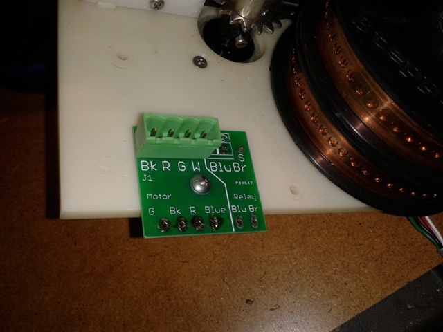
SteppIR places a small piece of two-sided sticky tape to assist in keeping the circuit board in place along with a small screw. I discarded the old sticky tape and applied new two-sided sticky tape and screwed the circuit board in place (Photo G).
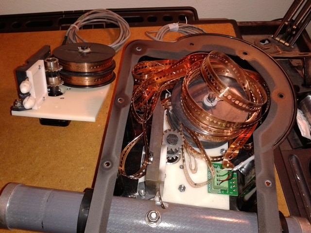
Next I needed to solder the wires from the motor to the circuit board. The wires from the motor were not long enough by themselves to reach the circuit board so I had to leave part of the control cable wiring connected to reach the board. I then soldered the wires to the circuit board and the assembly was now ready to be installed into the 2012 EHU shell.
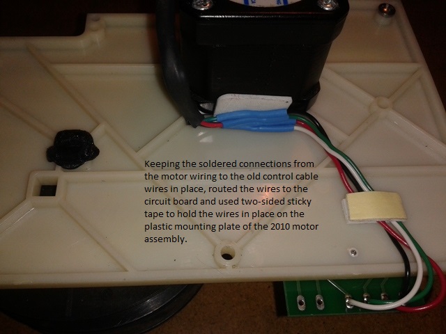
It’s worth noting the the location of the wires in Photo H. When I inserted the motor assembly into the EHU shell, I noticed the wires would have been pinched against the shell. So I had to move the wires slightly to the left of where it is shown in Photo H so they would be in a channel in the EHU shell and not get damaged when screwing the assembly in.
Installing the 2010 motor assembly into the 2012 shell was not difficult but it did take two hands and two tries. Therefore I was unable to take any pictures of this process. I first removed the plastic bullets that were temporarily installed on the ends of the copper tape. Holding the assembly by the spools with one hand to keep the tape from being pulled back through the contact plate, I guided the ends of the tapes with my other hand into the slots of the plastic (actually might be nylon) guide. Once the tapes were just inside the guide, I moved that hand to the sprocket and gently turned the sprocket counter clockwise to extend the tapes into the ESTs. Patience is required but it wasn’t real difficult. I extended the tapes a few inches out of the EST and reinstalled the plastic bullets using a drop of Loctite superglue gel as suggested by SteppIR. The EHU was now ready for testing.
To test the EHU, I used a SteppIR connector box that is normally installed at the base of my 35′ tower for my converted 2-element SteppIR yagi. For that installation, having the connector box at the base of the tower allowed me easy access. I removed it from the tower and brought it to the EHU which was set on a work platform. I used a DB25 to DB25 cable to connect the SDA-100 controller to the connector box. I ran an extension cord to the controller for power.
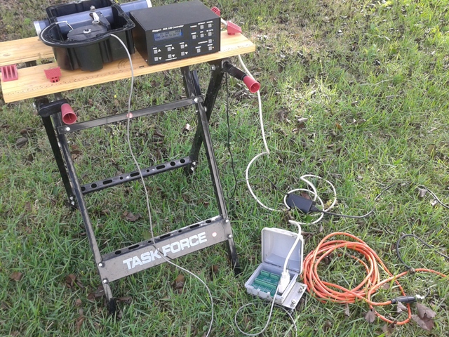
I first used the controller’s “Test Motors” function to test the motors and it worked. I then put the fiberglass tubes onto the ESTs and tested the EHU by moving the controller to different bands. I created a YouTube video to show the testing.
The video does have one error. It was the director EHU that had the broken shaft and not the reflector EHU.
After testing the EHU, I decided to go ahead and install it onto the antenna since the weather was perfect for the job. Putting the EHU back on the antenna was easier than removing it. I first installed the EHU by itself onto the mounting plate on the boom. I then brought up the 2 fiberglass tubes and installed them onto the EHU. When I got off the tower, I had to put the ends back up for my 40, 80 and 160 meter antennas. After connecting the SDA-100 controller in the shack, I had to go back and reset the lengths for the elements on 10, 15 and 20 meters using Create/Modify in the controller. I had previously changed the lengths in order to use the antenna as a 2-element yagi. The whole job, start to finish, took about four hours.
When I finished, there was about an hour of sunlight left. I jumped back into the WAEDC RTTY contest and worked several JA stations on 15 meters. The next day I continued in the contest and the antenna performed perfectly. I still intend on repairing the original 2012 motor assembly with a new reel shaft and copper tapes. But for now, I’m back on the air with 3-elements. I hope it stays that way for a while.
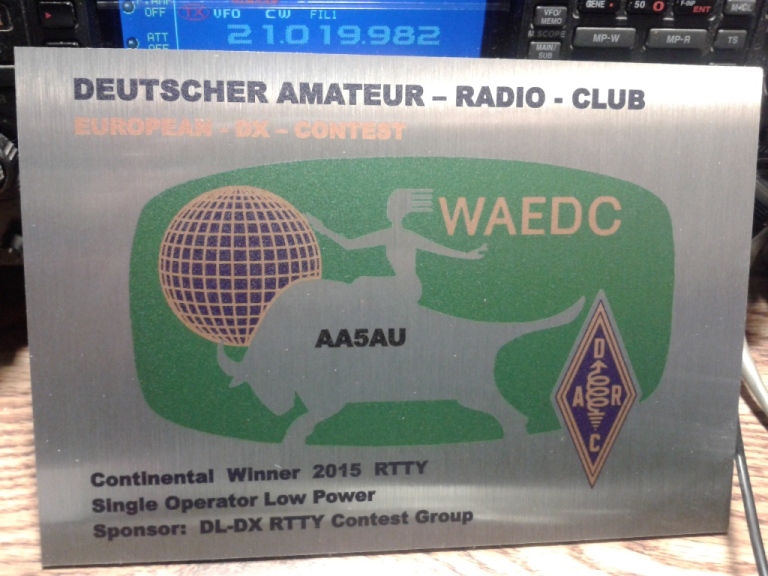
NOTE: Despite taking the time out of the WAE RTTY Contest to repair the antenna, I was still able to win first place Single Operator Low Power North America in the contest. Here is the plaque.