Reassembly comprised of installing the gaskets and covers on each EHU, installing the EHU’s onto the boom, fabricating and installing a new junction box, routing control cables to the new junction box, preparing three additional control cables to go from the new junction box on the boom to a SteppIR junction box which will be mounted at the base of the tower, terminating all the cabling and final testing of the EHU’s.
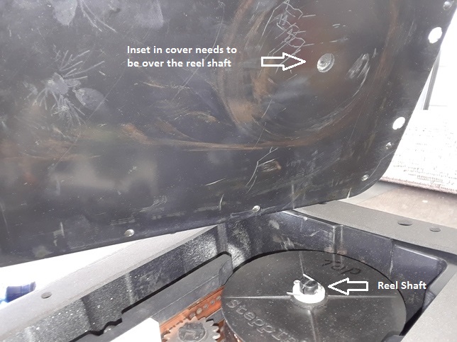
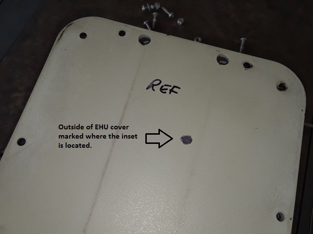
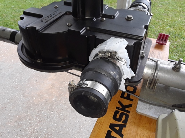
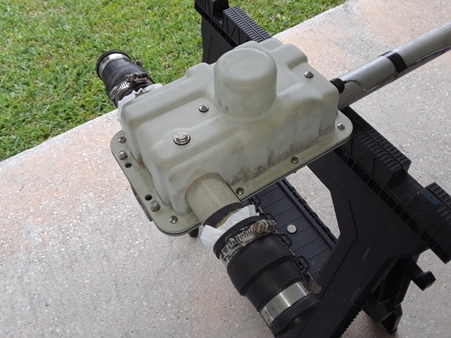
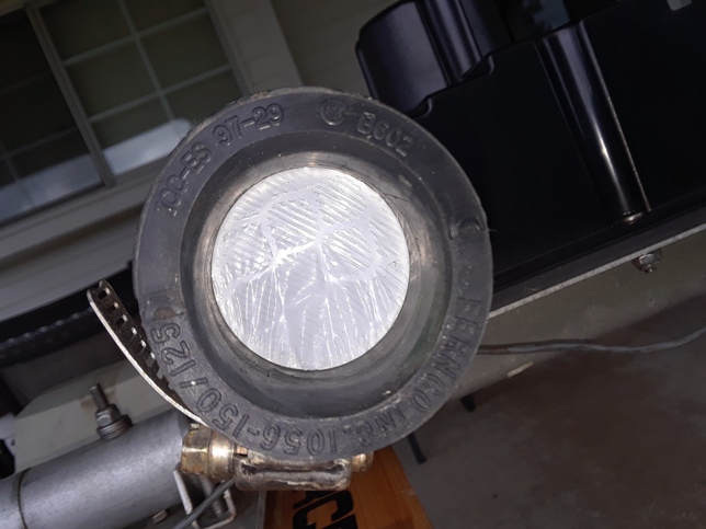
New SteppIR gaskets were used when the covers were installed. On older style (gray) EHU’s, the cover must be installed with the inset in the lid over the spool shaft as shown in Photo 1. To make sure I knew the covers were installed correctly, I marked the outside of the covers to show the location of the inset (Photo 2). The covers for older style EHU’s (gray ones) are rectangular and can easily be installed incorrectly. The cover shape of newer EHU’s (black ones including the DVR EHU on this antenna) is unique so the cover can only be installed one way and cover orientation is not an issue.
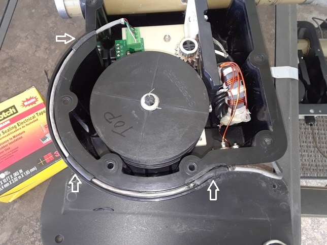
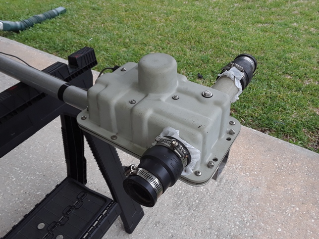
On the DRV EHU, I replaced the old rubber tape with new mastic tape in the groove where the control cable enters the unit as shown by arrows in Photo 3.
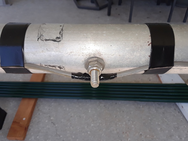
Once the EHU’s were sealed and mounted onto the boom, the control cable for each EHU was then routed back to where a new junction box would be installed on the boom. I used electrical tape to secure the control cables to the boom. Where there is a nut & bolt in the boom, I put electrical tape around the control cable jacket for more protection.
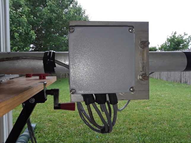
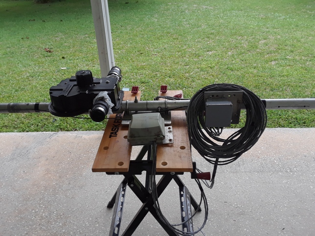
A weather-proof junction box was purchased from Lowes for $7 and mounted onto an aluminum plate. The plate was a boom-to-mast plate from an old antenna.
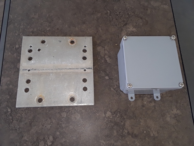
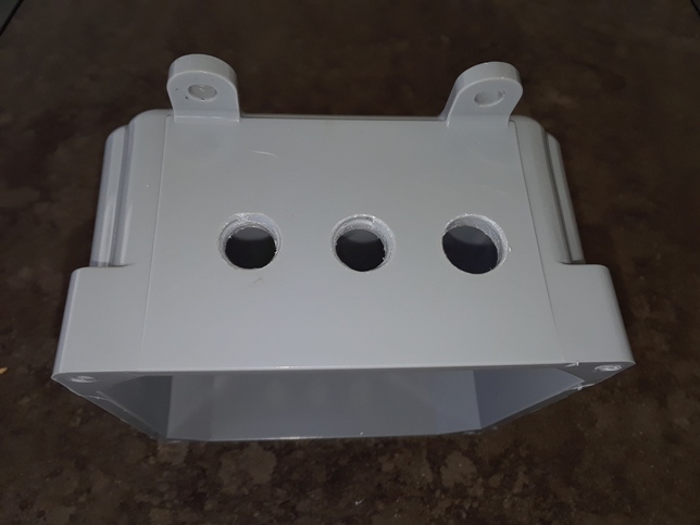
Prior to mounting the junction box onto the plate, three holes were drilled in the bottom for the control cables. One hole is larger than the others because the control cable from the DIR EHU had to be extended using larger diameter cable because it wasn’t long enough to reach the junction box. The edges of the holes were smoothed to keep from cutting into the cables.
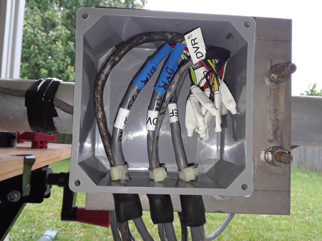
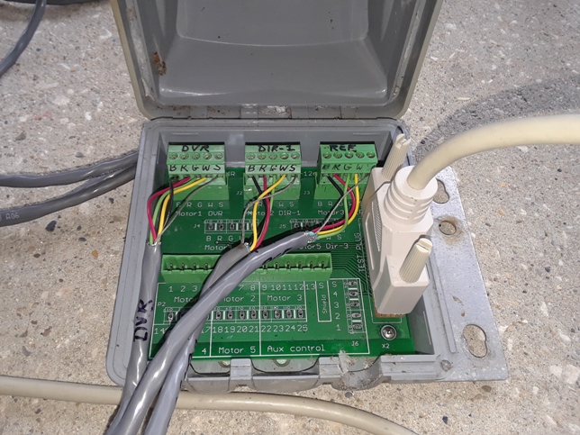
The control cables coming from the EHU’s and the control cables that would be going down the tower were labeled and terminated inside the new junction box. The ends of the stripped wires were dipped in synthetic connector grease before being crimped into white B-connector wire splices. Cable ties were used as strain reliefs and mastic tape was used to seal the bottom holes.
The three control cables from the junction box on the boom to the SteppIR junction box located at the base of the tower were made from new Belden 8786 cable I had in my junk box. Each cable was 40′ in length because the antenna will be at 35′.
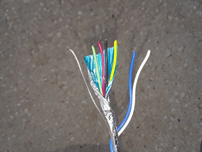
Belden 8786 is 6-conductor cable with four of those conductors shielded. It also includes a bare drain wire. The colors of the shielded wires are black, red, green and yellow. I cut off the blue and white wires since they are not shielded and not used. The yellow wire connects to the white wire coming from the EHU’s. All the other colors matched between the two types of cable.
Belden 8786 is used on offshore supply vessels to run remote radio units off the main 2-way radio. Sometimes these remote units are located outside so the cable is well-tested in outside saltwater environments.
After all control cables were terminated inside the control box, the box was sealed.
I connected the 40′ 8786 control cable ends to the SteppIR control box and EHU’s were tested.
Here’s a short video of the TEST MOTORS function of the SDA-100 controller used to test the EHU’s.
Video 1
After the motors were tested, I cut a plastic garbage bag into small pieces and placed them over the openings in the EST’s. I used the rubber boots to hold the plastic in place to keep moisture and insects out of the EHU’s. I did this since I wasn’t sure when I would be able to install the antenna.
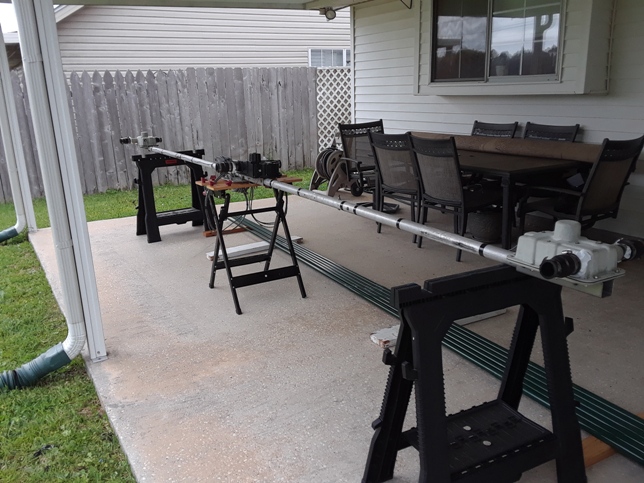
Reassembly on the ground is complete. The antenna is ready to be installed. Waiting on weather and other factors.