On Friday May 4th, 2018, I took the day off from work to install the antenna. The forecast was for clear to partly cloudy skies and temperatures in the low to mids 80’s with only a 10% chance of a stray shower. I anticipated good weather for the install.
I started at 8 AM. The first thing I did was to re-install the 30/40 meter return mounting bracket bracket back onto the boom. I had removed it when I put the boom together because the antenna was not going to have the 30/40 meter option. I later realized I use this bracket to lift the boom up the tower.

The rope bucket was brought out from the garage and placed next to the tower. I use high quality manila rope for pulling up the boom. It’s bigger than needed but fits the pulley in the gin pole nicely.
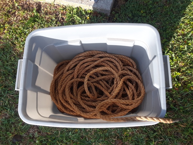
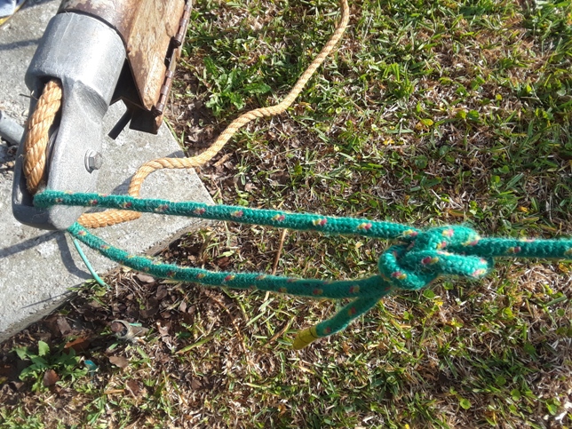
I ran the Manila rope through the gin pole then tied my smaller green rope above the pulley. The green rope is used to pull the gin pole up the tower by hand.
Video 1
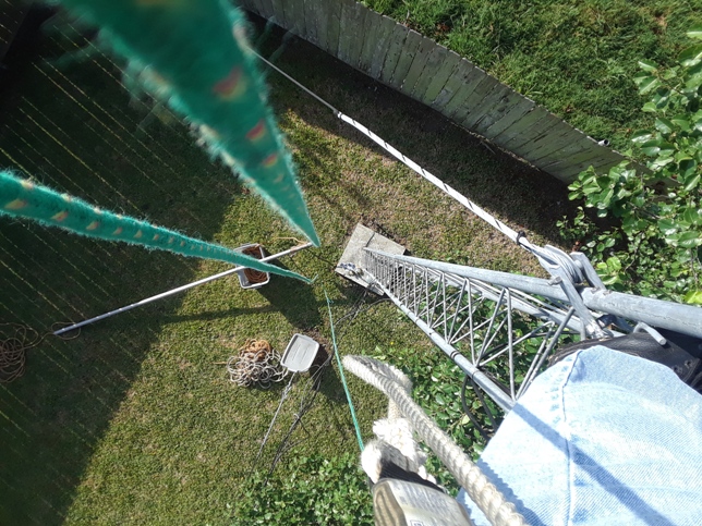
The gin pole is then pulled up the tower and mounted to the leg of the tower.
Video 2
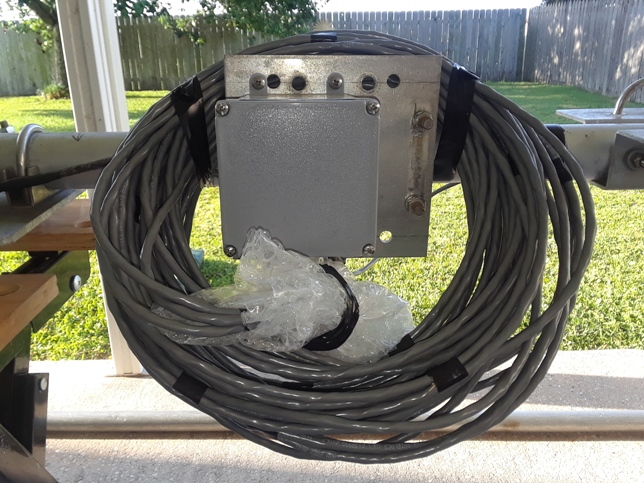
Before pulling the boom up the tower, the control lines from the junction box were secured to the boom and bubble wrap placed around the connectors that connect the wires to the SteppIR control box mounted at the base of the tower.
Video 3
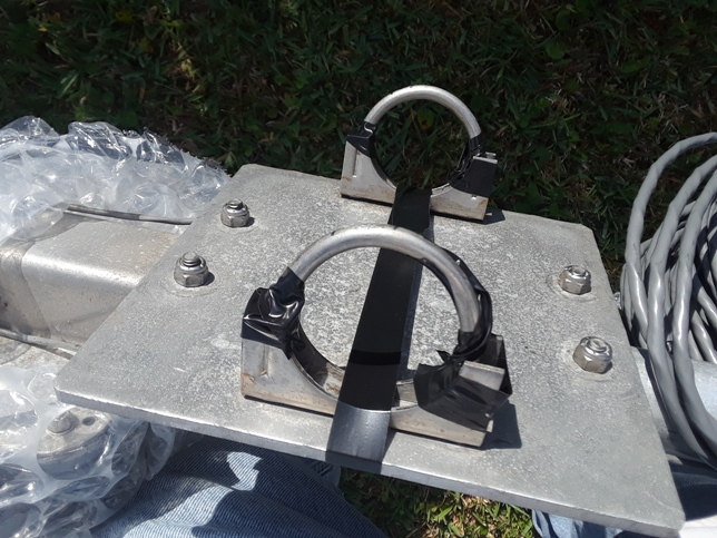
To facilitate sliding the U-bolts on the boom-to-mast plate onto the horizontal mast coming out of the PVRC mount, tape was used to hold the U-bolts open. Additionally, the saddles were taped to the boom-to-mast plate to make things easier when on the tower.
Video 4
While preparing the boom for lifting, a bird dropped out of the sky and onto the ground near me. It appeared to be stunned or injured. Not sure if it flew into the tower or was attacked by another bird. I picked it up and moved it into the shade in hopes it would recover.
Video 5
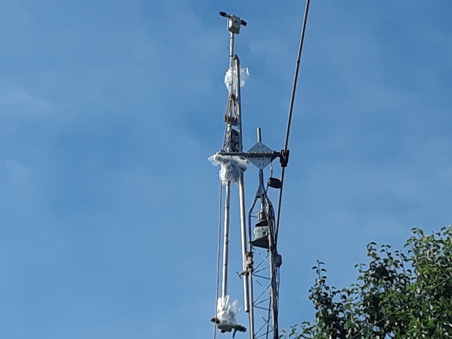
Using the gin pole, the boom was pulled up the tower to a position where the boom-to-mast U-bolts were slightly below the horizontal mast of the PVRC mount.
Video 6
The boom is then lifted and slid onto the horizontal mast of the PVRC mount. This is not as difficult as it may appear. The boom, even with the EHU’s installed is not all that heavy and it’s supported by the rope coming out of the top of the gin pole. When I pulled up the boom, I tied it off perfectly. It was exactly where it needed to be for an easy lift onto the horizontal mast.
Video 7
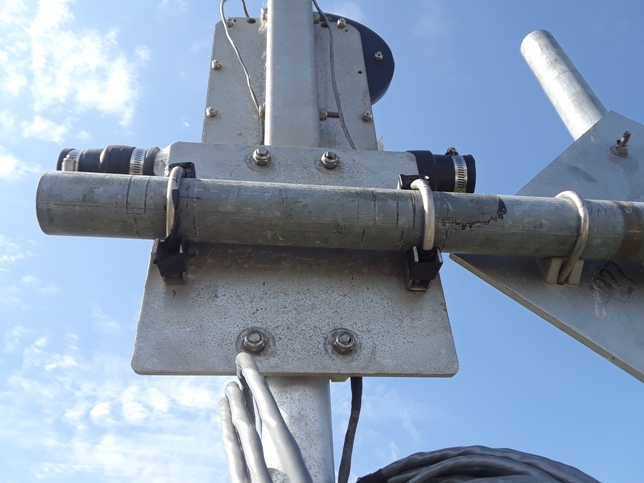
Once the boom-to-mast plate is installed onto the horizontal mast, the U-bolts are tightened enough to allow the boom to be rotated on the mast but not swing freely. The bubble wrap was removed and the gin pole was lowered to the ground.
Video 8
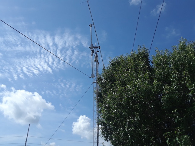
After the gin pole was lowered, I brought the boom horizontal by rotating it on the horizontal mast (Video 9). I did this in order to check to see if there was any interaction between the boom and the Cushcraft D40 40-meter dipole that I installed the previous weekend. I then came down the tower and into the shack to run an SWR scan on the D40. The SteppIR boom did not appear to affect the D40 (Video 10).
Video 9
Video 10
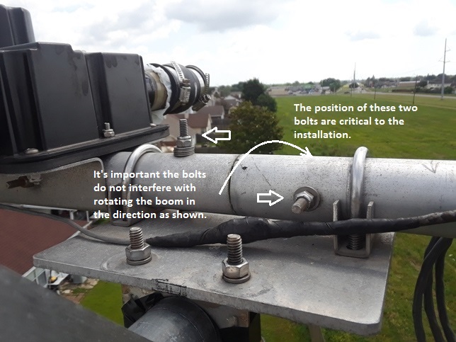
Back up on the tower, the two bolts holding the boom together are re-checked to make sure they are in the correct position. This was checked on the ground, but needs to be re-checked on the tower because if the bolts are not in the right position, the antenna cannot be installed.
The bolt on the left must be pointing upward and the bolt on the right must be pointed as shown because the boom will be rotated in the direction shown in Photo 11.
Video 11
Video 12
The installation of the boom is now complete. Continue to Installation Page 2 here.