Troubleshooting High SWR on 3-element SteppIR Yagi Antenna (View in PDF here)
On Saturday morning March 26, 2016, I found higher than usual SWR on all bands on my 3-element SteppIR yagi. Re-calibrating the antenna didn’t cure the problem. I ran a set of SWR graphs for each band to use as a reference. I had this very same symptom just 5 months ago. What I learned back in November 2015 was that SWR at 3:1 or lower on each band meant that the driven element was working but one of the other elements was not. The other thing that I learned was by moving the elements in and out manually with Create/Modify and watching the SWR characteristics, it’s possible to tell which elements are working and which are not.
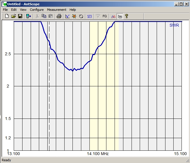
I set the antenna on 20 meters (14.100 MHz) and moved the Reflector in and out using Create/Modify and the SWR graph (shown below) did not change. I then moved the Director in and out using Create/Modify and the SWR graph did not change. Moving the Driven element in and out drastically changed the SWR graph. I suspected that neither the director or reflector elements were working.
The last time I used the antenna was the previous weekend in the BARTG HF RTTY Contest. One day this past week we had severe weather with bad thunderstorms, lightning and high winds for most of the day. I wondered if the weather could have been the culprit. I wondered if lightning had caused a windings on the director and reflector motors to go open. It seemed unlikely since I had no other indication that there had been a lightning strike. I keep all the cables disconnected when bad weather is forecast so I suppose it was possible the antenna got struck by lightning and it didn’t make it into the shack but I doubted that happened.
Referring to SteppIR’s troubleshooting page, I then measured the resistance of each cable pair going up to the antenna from the controller. Each EHU (element housing unit) has one stepper motor and each stepper motor has two windings. The nominal resistance should be around 20 ohms on each of the six cable pairs when measured at the controller end of the cable.
Resistance Checks
- Driven Element
- Resistance between pins 1 & 2 = 20 ohms
- Resistance between pins 3 & 4 = 20 ohms
- Director Element
- Resistance between pins 5 & 6 = open
- Resistance between pins 7 & 8 = 20 ohms
- Reflector Element
- Resistance between pins 9 & 10 = 20 ohms
- Resistance between pins 11 & 12 = open
There was the problem. One pair going to the Director was open and one pair going to Reflector was open. I took the shell off the DB25 connector that goes into the back of the controller and inspected the solder connections. They looked good.
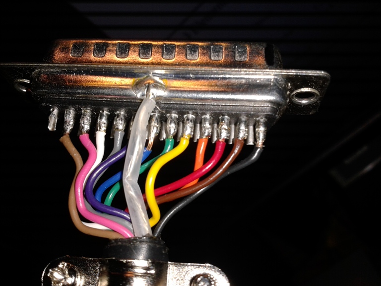
The next step was to check the cable from the connector to the connector box located on the boom of the antenna. Something else I learned from last November was to place a short across all suspect cable pairs so I could check to see if the cable going up the tower was open or good. With the cable disconnected from controller, I shorted wires 5, 6, 11 and 12 together with a clip lead (Photo B below).

I climbed the tower and disconnected all connectors from the connector box. I measured a short between wires 5, 6, 11 and 12 suggesting the cable going back to the shack was good. I then measured the cable pairs going to each EHU. I found the first pair to Director EHU and second pair to Reflector EHU were open.
I came down off the tower to plan my next move which I already knew was to remove both the Director and Reflector EHU assemblies. It had stormed earlier that morning but the weather was clearing and the sun was peaking out occasionally. I checked the radar and the rain associated with a stalled out warm front just to the south was still out in the Gulf of Mexico. Since the forecast was for rain on Sunday, I knew I needed to take advantage of the break in the weather to get the EHU assemblies off the tower even though I really didn’t feel like doing tower work. I had installed the antenna on a PVRC mount which makes it easier to work on while it’s on the tower. Removing the EHU assemblies, with the fiberglass tubes attached, is not a major undertaking but it is time-consuming to do it safely.
So I climbed tower and removed both director and reflector EHU assemblies with fiberglass tubes attached (took 2 hours by myself). It would have taken less time had I not dropped the screw driver I was using to remove the first element. I used my spare screwdriver to complete the removal of the first EHU. The spare screwdriver was awkward to use so after I lowered the first EHU assembly, I decided to go down the tower and retrieve the good screwdriver.
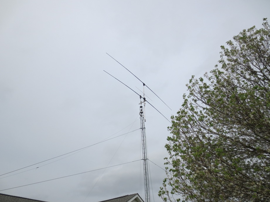
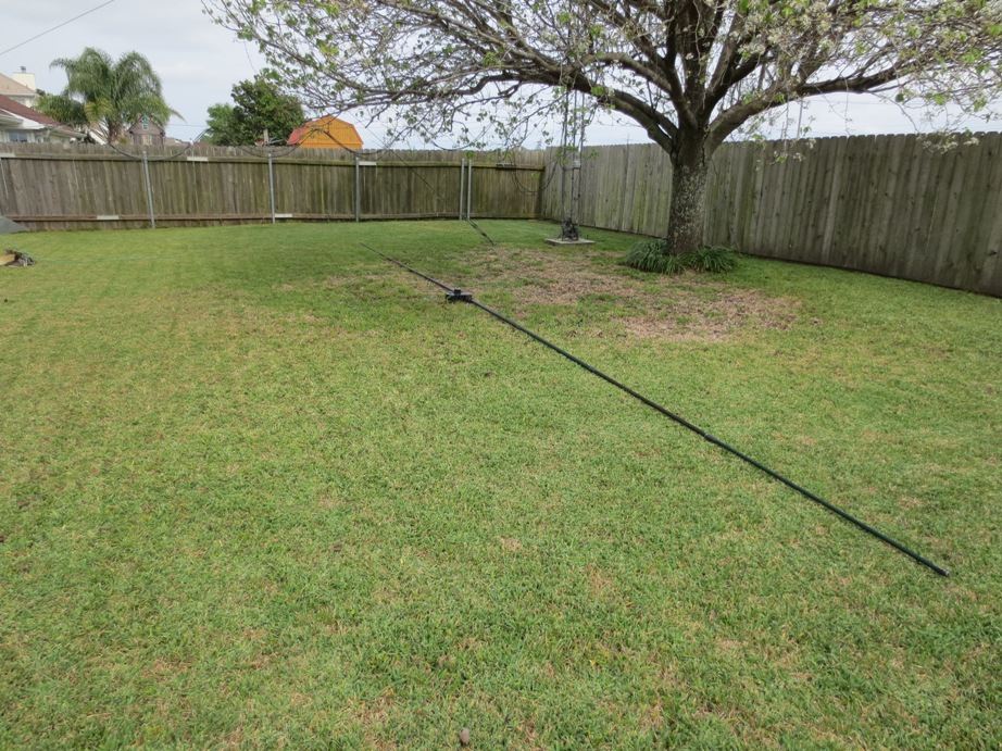
While on the ground I took a picture of the antenna with the Reflector removed (Photo C – above) and a picture of the Reflector on the ground (Photo D – below). The tower in the background (below), next to the tree, houses my 2-element SteppIR yagi. I had checked it earlier and thankfully it was working fine. I can only deal with one SteppIR problem at a time!
Back up on the tower, I was able to successfully remove the Director element and lower it to the ground without dropping any more tools or any screws. On the ground, I then removed the fiberglass tubes from each EHU and brought the EHU assemblies into the shack and on the work bench.
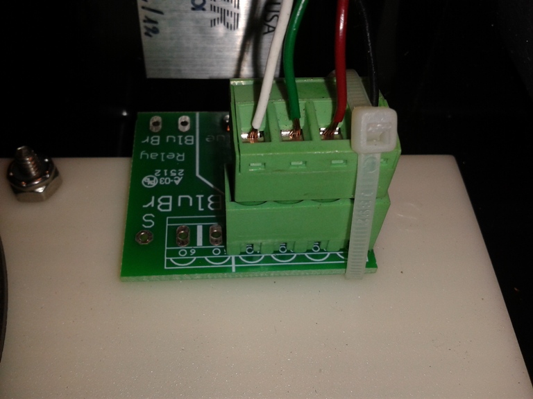
I opened the Director EHU first. I saw the inside connector had worked itself partially out of its socket (see Photo E below). I gently pushed on it and it seated back into the socket. I measured the winding resistance at the connector and it now checked OK on both windings. I couldn’t believe it. I then opened the other EHU and it had the same exact problem except it was cocked in the opposite direction. These connectors sit upside down in the EHU when installed on the antenna. Apparently, shaking from the rough weather we had this week, along with the force of gravity, caused the connectors to unseat from the jack. They did not fall completely out but they were not seated in all the way. I know it wasn’t installed this way. The antenna has been up for over three years and I just reworked the reflector EHU in November. These connectors are not used on earlier model yagi antennas. This antenna was purchased and installed in 2012. My 2-element SteppIR which was originally purchased as a 3-element in 2010 does not use these connectors. The cable is hardwired to the motor on that earlier model antenna.
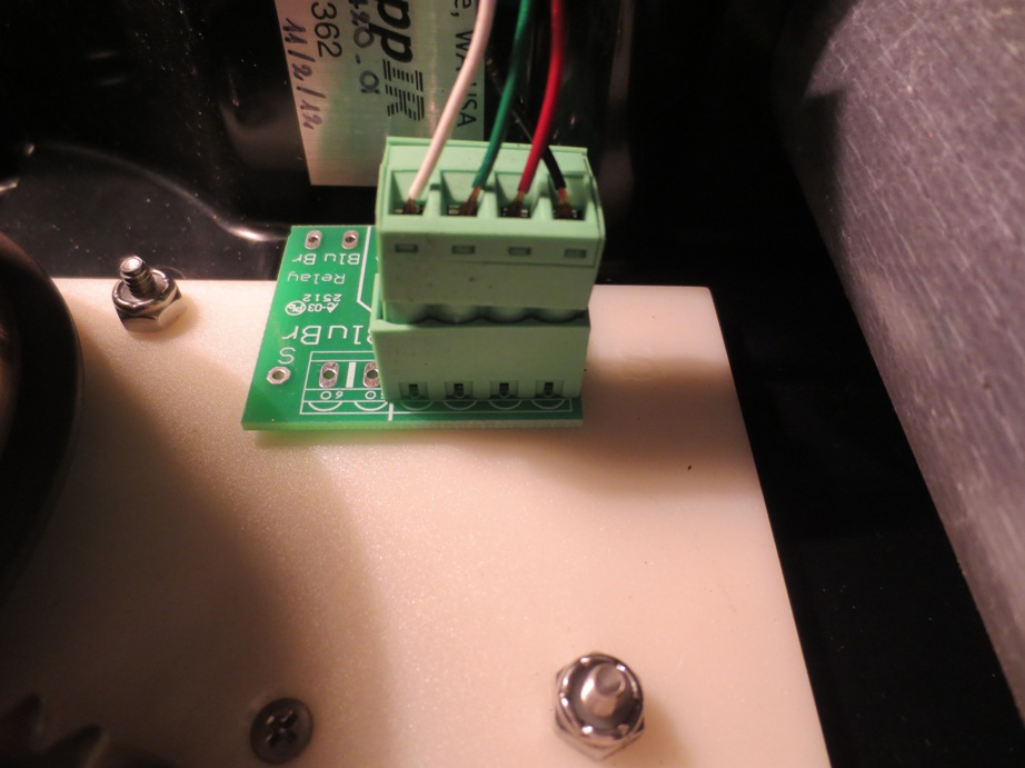
Photo F (below) is a picture of what the connector should look like when fully seated. I debated on whether to use a dab of silicone adhesive or a tie wrap to secure the connector. I decided on the tie wrap to keep the connector from becoming dislodged in the future. Although I’m disappointed this happened, I’m glad it wasn’t worse. Makes me wonder about the condition of the connector inside the driven element EHU.