On Saturday January 20, 2018, the spool shaft broke in the driven EHU (element housing unit) of my 3-element SteppIR yagi. On Monday I called Bart at SteppIR and he was very helpful in getting a replacement spool plate and EHU gasket to me quickly. The replacement spool comes already mounted on the base plate. On Thursday, January 25, I replaced the spool plate inside the EHU. Even though I made a similar repair in November 2015, I still used the instruction guide created by Pedro, EA1YO, showing the replacement of a sprocket shaft because much of the procedure is the same. (NOTE: The spool shaft and motor sprocket shaft are two different shafts but you still have to remove the base plate to replace either one of them.)
Procedure for Replacing the Spool Shaft and Plate
Please note the EHU shown here is a 2012 model and may not be exactly the same as others. Older EHU’s with gray shells do not have the circuit board and connector shown in these instructions. There may be other differences as well. Also, the term spool and reel mean the same thing and are interchangeable.
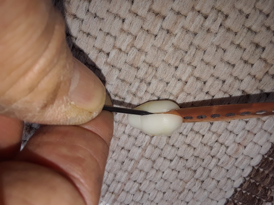
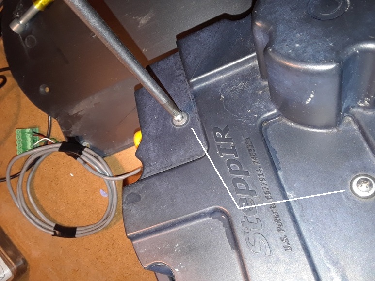
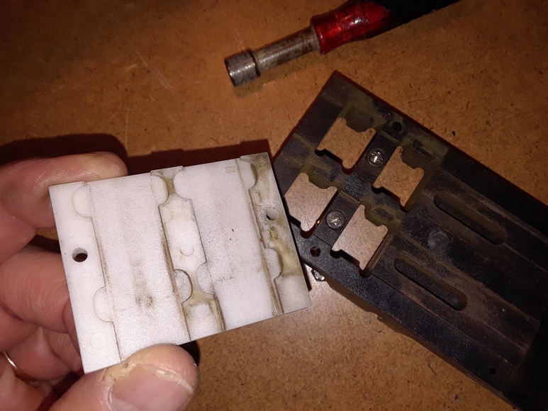
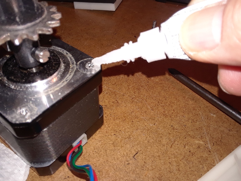
Step 1 – Remove the bullet from each end of tape.
Use a very small flat head screwdriver to pry apart the two pieces enough to then use a larger flat head screwdriver to separate them (photos 1 & 2). Inspect the bullets. If they are damaged, order new ones from SteppIR. If they are OK, keep them in a safe place to reuse.
Step 2 – Use your forefinger and thumb on the sprocket to wind the tapes from the element support tubes (EST’s) and back into the EHU so you can remove the spooled reels. IMPORTANT: MARK THE TOP OF EACH SPOOL “TOP” OR SOME OTHER MARKING TO SHOW IT IS THE TOP OF THE SPOOL. THIS MAY BE IMPORTANT WHEN REINSTALLING THE SPOOLS.
If the reel shaft is broken, the reels should come out of the EHU easily. If not, remove the pin atop the spool shaft and lift gently on the top spool to remove it. You may need a pair of needle nose pliers to move the spring to the center of the hole in the spool in order for the spool to come off. Do the same for the lower spool. My reels were marked with an “L” on the side facing away from the plate.I don’t know if it’s important but you may want to mark the reels if they aren’t already so you can put them back the same as they were. Inspect the tapes to make sure they are not damaged. Unless the tapes are severely kinked, they’re probably OK. , Wind the tape back onto the reels and use a piece of tape to secure them. Set the reels aside.
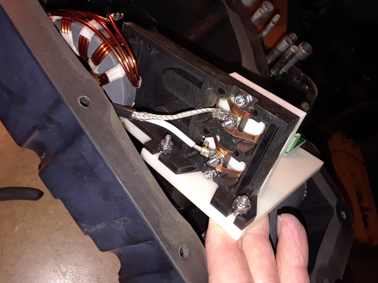
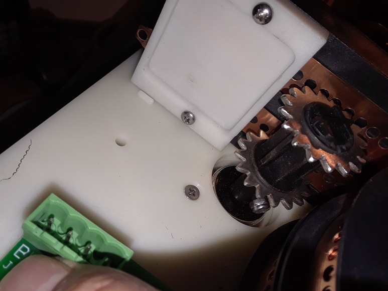
Step 3 – Remove the plate assembly by removing the 3 nuts inside the housing. If the EHU contains a balun, you will need to disconnect the contacts before the removing the plate assembly from the EHU.
Use a Phillips screwdriver and 5/16″ nut driver to remove the three nuts holding the plate assembly to the outer shell. It’s not necessary to remove the screws but you can if you want. If you remove the screws, it’s suggested you do not remove the flat washer and rubber washer as shown in photo 5. They will likely stay in place on the outer shell by themselves. Once the three nuts are removed on the inside, you can then lift the plate out of the EHU if the EHU does NOT contain the RF connector and balun.
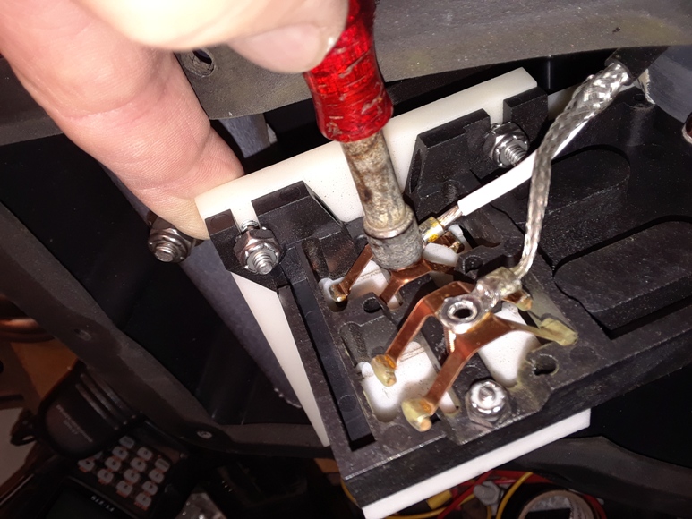
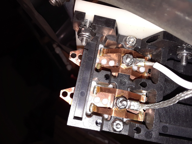
If the EHU contains the RF connector and balun, pull the plate out slowly so that the nuts holding the wires to the contacts are exposed as shown in photo 6. Remove the nuts to release the contacts from the contact plate using a 1/4″ nut driver as shown in photo 7. If the nut driver will not fit the nut due to the terminal, use a 1/4″ mini wrench or a pair of needle nose pliers to back the nut off enough for the nut driver to fit. The contacts are soldered directly to the wires from the balun. Once the screws are removed, gently push the contacts out of the way and the entire plate assembly can be pulled from the EHU.
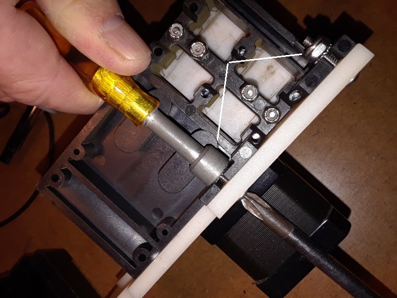
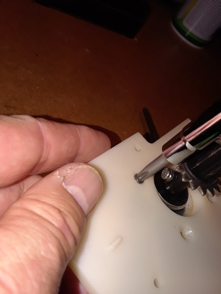
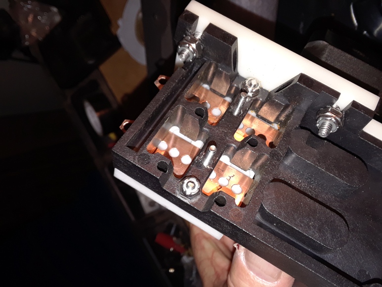
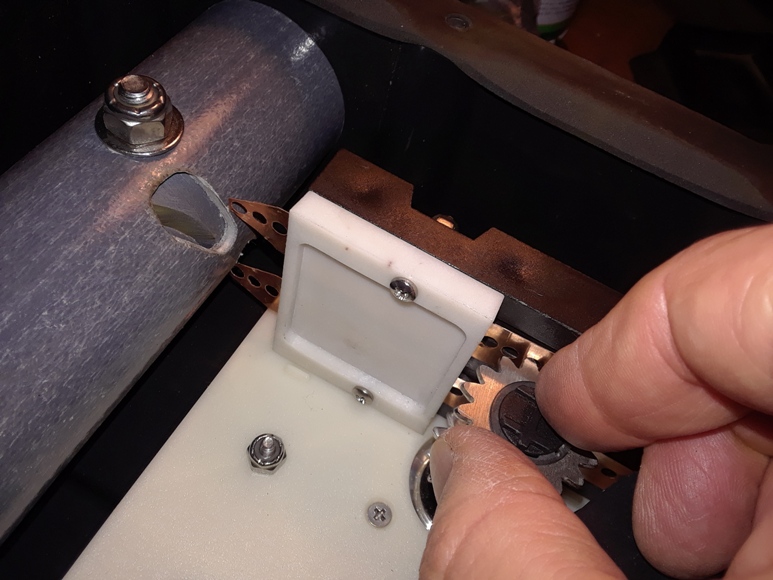
Step 4 – Remove the contact plate from the base assembly by removing the two nuts, screws and star washers shown in photo 8 using a Phillips screwdriver and 5/16″ nut driver.
If the nut driver doesn’t not fit securely on the top nut, a needle nose pliers can be used to hold the nut while unscrewing it with the screwdriver. If the contact plate and cover are dirty as seen in photo 9, they can be separated by removing the two screws and 1/4″ nuts that hold them together and cleaned with compressed air or wiped down with a damp cloth or both.
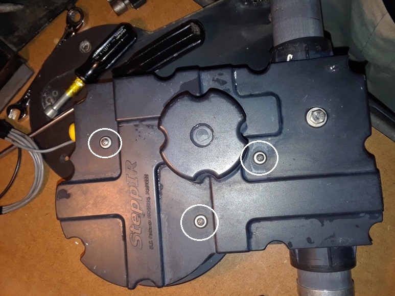
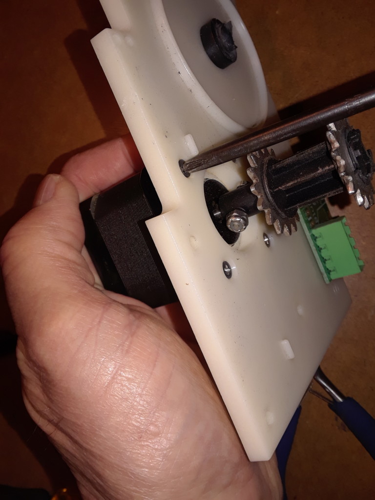
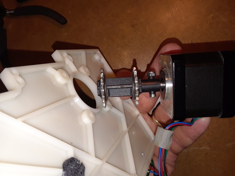
Step 5 – Remove the stepper motor from the base plate by removing the four screws.
Be careful because the screws were installed with glue or Loctite to hold them in place. Be sure the Phillips screwdriver used properly fits the screw head. It may take some effort to break the screws loose. Be careful not to strip the screw heads. If the screws don’t want to break free, place the bottom of the motor on a secure flat surface then use your weight to push down on the screw head while turning the screwdriver counter clockwise as shown in Photo 11.
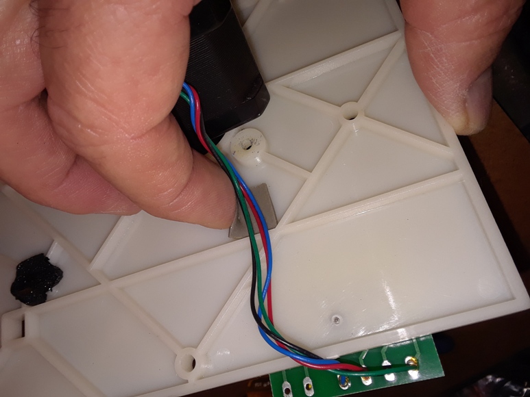
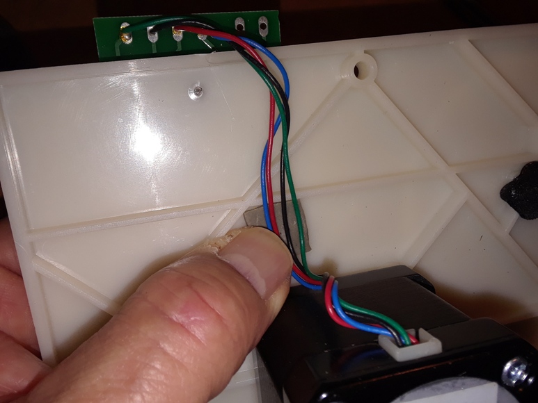
Step 6 – Turn the plate over and carefully remove the two-sided sticky tape holding the wires to the base plate (photo 12) then remove circuit board.
Be sure to leave the sticky tape stuck to the wires so they can be stuck to the new plate. Now remove the small printed circuit board by unscrewing the small screw holding it to the plate and carefully prying it off the plate, keeping the sticky tape stuck to the bottom of the circuit board and not the plate. (photos 13 & 14). Everything is now removed from the old plate and it can be discarded.
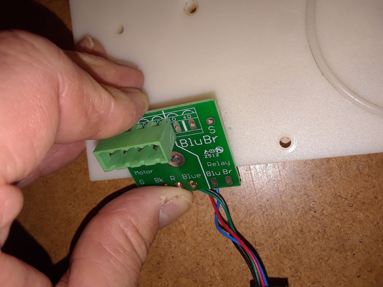
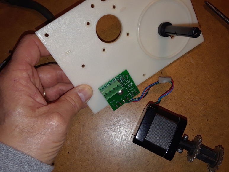
Step 7 – Begin reassembly by mounting the printed circuit board onto the new plate using the small screw and sticky tape.
There should already be a very small hole drilled into plate for the screw. If your EHU does not include a printed circuit board, this is a good time to add one. Order one from SteppIR along with the associated connector and solder the wires from the motor to the circuit board then add the connector onto the cable coming into the EHU from the controller.
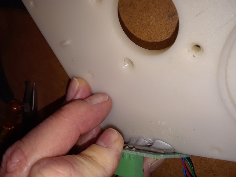
Step 8 – Turn the plate over and insert the motor. Before installing the screws, place a very minute amount of Loctite into each of the screw holes in the motor (photo 17).
After applying Loctite, set the plate on top of it and install the screws. Make sure the wires coming out of the motor are directed toward the circuit board. After installing the screws, use the sticky tape to secure the wires to the plate (photo 18).
Step 9 – Install the contact plate onto the base plate using the two screws and 5/16″ nuts.
Refer to photo 8 if you are unsure how the contact plate installs onto the base plate. Note that if you are working on an EHU that does not include the RF connector and balun, then the contacts will still be attached to the contact plate. If you are working on an EHU that includes the RF connector and balun, the contacts will not be attached to the contact plate.
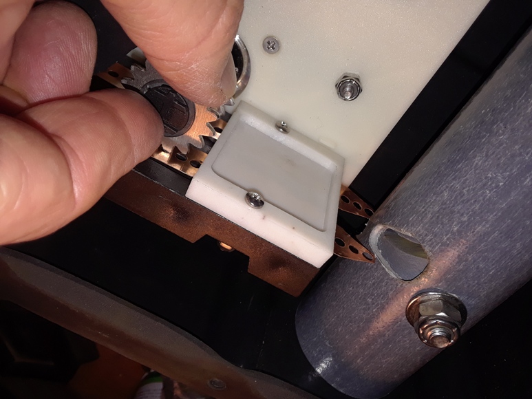
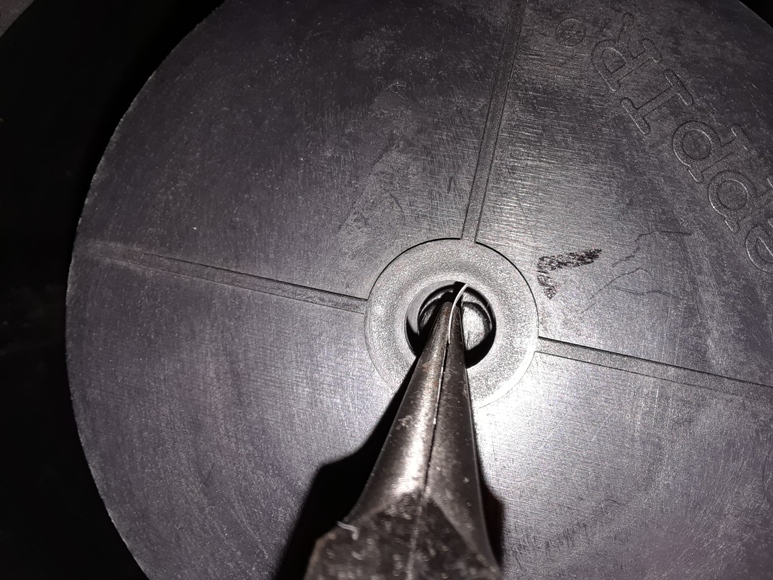
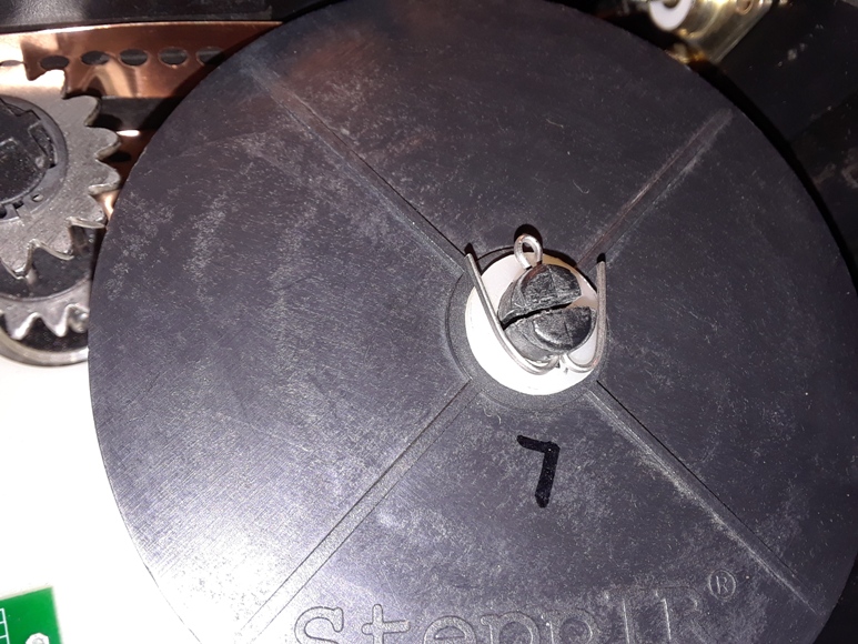
Step 10 – Install the two spools of copper tape onto the reel shaft.
Install the first reel of tape onto the spool shaft using a pair of needle nose pliers to position the spring into the slot of the shaft as shown in photo 19. Once the spring is in the slot, gently push the spool all the way down onto the shaft. Turn the spool 8 times counter clockwise and hold the spool in place, remove the adhesive tape, and insert the copper tape into the sprocket just enough to hold the reel in place. Now install the second reel on top of the first reel in the same manner.Turn the top spool 8 turns counter clockwise, remove the adhesive tape and insert that tape into its sprocket to hold it in place.
Step 11 – With the spools in place on the shaft, install the washer and locking pin.
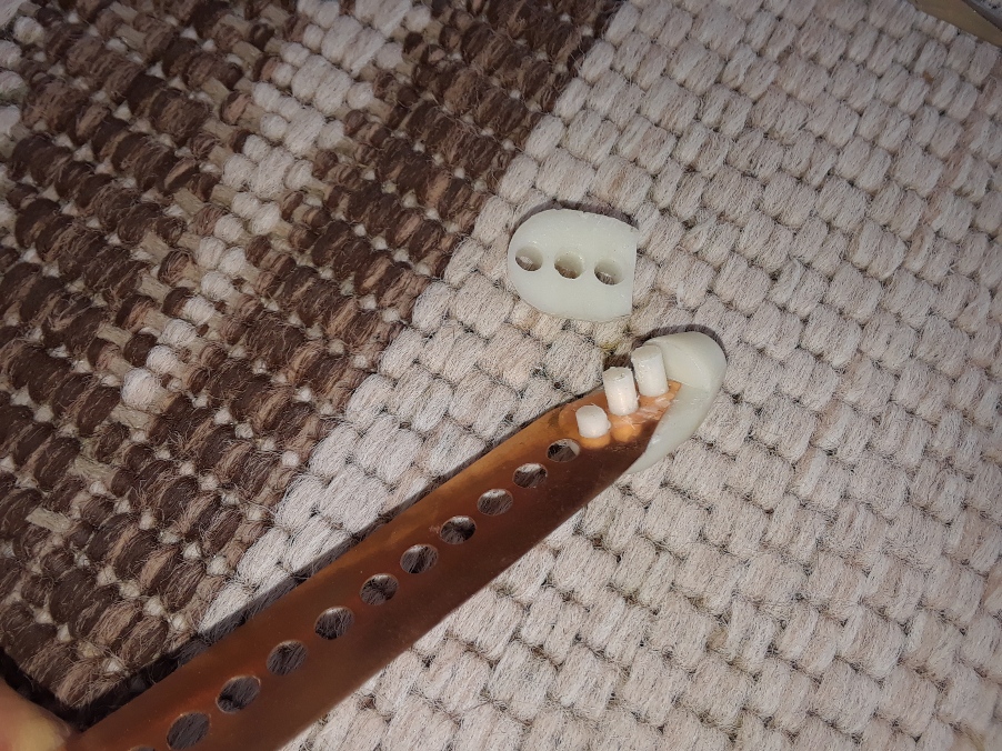
Step 12 -This is where my procedure differs from Pedro’s. Pedro was able to maneuver the tapes under the contacts using a pair of tweezers. Since I had to remove the contacts in Step 3 because they were attached the balun, I slid the tapes through the contact plate as shown in photos 21 & 22, then installed the contacts on top of the tapes as shown in photo 23.
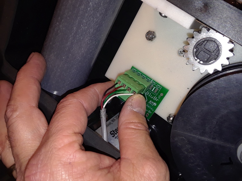
Step 13 – The plate assembly is now complete. Reinstall the assembly back into the EHU using the 3 screws through the outer shell and reinstall the plug into the printed circuit board.
Step 14 – Use the sprocket to move the tapes with one hand while guiding them into the slots of the EST with the other hand. Continue spooling until the tapes show a few inches out from the ends of the EST’s as shown in photo 26.
Step 15 – Attach a bullet onto the end of each copper tape. Add a drop of super glue to ensure the bullets do not come off the tapes. Squeeze the bullets tightly with pliers. Once the super glue dries, use the spocket to bring the tapes back into the EST to where the bullets come to a stop inside the EST.
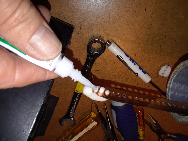
Photo 27
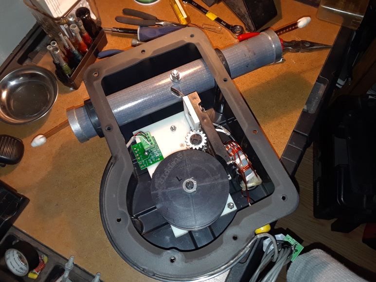
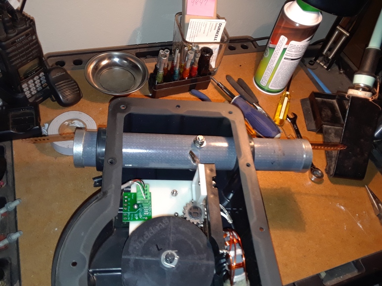
Step 16 – Test the EHU to make sure it works. The first video (below) is with the EHU upside down. The second video is the EHU right side up as it would be on the tower.
My test set up includes a SteppIR Connector Junction Box, the SDA-100 controller, and a 6′ DB25 male-to-male cable. The connector box is one that is used with my converted 2-element SteppIR. It is installed at the base of a 35′ tower and can be easily removed and used for testing.
Video #1
Video #2
This completes the rebuild. On Saturday, January 27, 2018, I reinstalled the EHU back onto the antenna and it worked fine.
73, Don AA5AU