Why Use a PVRC Mount?
The PVRC Mount is a tilt-head type antenna mount that allows any sized HF Yagi antennas to be easily installed on towers. A PVRC Mount can be quite useful when there isn’t enough room on the ground to “tram” the antenna up the tower. Large yagi antennas can be built on the tower with just one tower person – no need for a large crew of ground personnel, cranes, or acrobatics on the tower. If an antenna needs maintenance, the elements are easily reachable when the antenna is installed on a PVRC mount. The PVRC mount got its name from the Potomac Valley Radio Club, and mainly Ed Bissell W3AU, who used these mounts to build large monoband yagis in a heavily wooded area.
PVRC Mount Construction
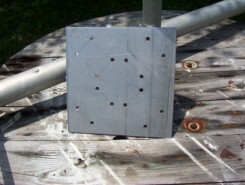
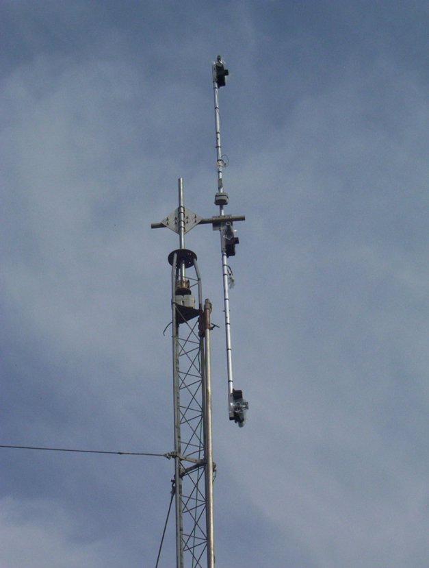
The heart of the PVRC mount is the plate which connects the vertical mast coming out of the tower with the horizontal mast where the antenna will be mounted. My PVRC mount plate was fabricated using a 12″x12″ piece of 3/8″ 6061-T651 aluminum plate purchased pre-cut from Metals Depot (http://www.metalsdepot.com/products/alum2.phtml?page=plate) for about $40. I didn’t use any kind of template to drill the holes. I tried to make it as symmetrical as I could and used a drill press to drill the holes. I purchased eight 2″ saddle clamps and stainless 3/8″ U-bolts from DX Engineering (p/n DXE-SAD-200B).
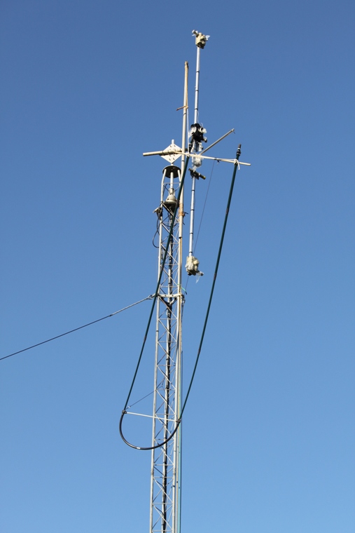
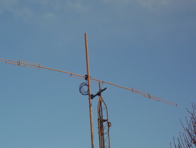
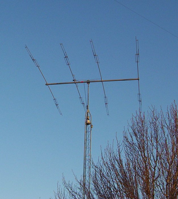
In the picture below, the plate is mounted to both a vertical and horizontal mast. The antenna in the picture is a KT-36M2. I had originally built the PVRC mount to install the KT-36M2. However, after considerable thought, I elected not to install the antenna because it was too big for my Rohn 25 tower. I later converted the KT-36M2 into a smaller KT-34M2 in November 2010 and used a temporary PVRC mount to install it (shown later on this page).
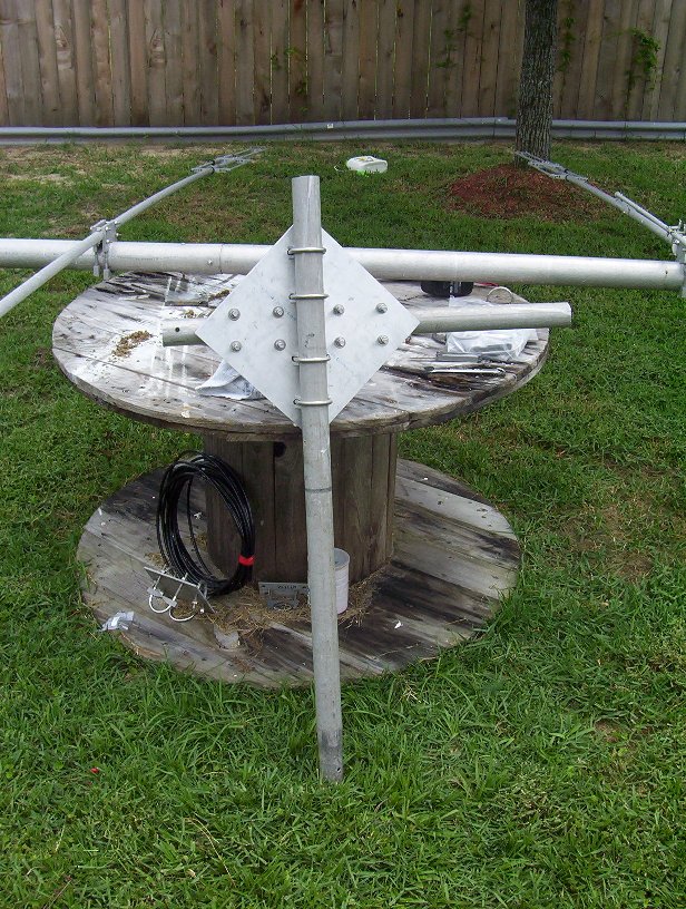
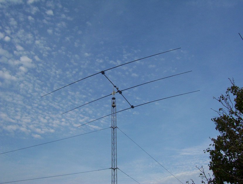
In the picture below, the PVRC mount is shown as it would be installed on a tower. The vertical mast was placed into a hole in the middle of the wooden spool for support while on the ground (normally this vertical mast is installed into the top of the tower and into a rotator). The boom-to-mast plate is mounted horizontally and the antenna boom sits on top of the this plate as shown.
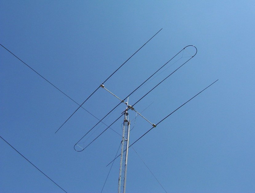
Installing a 3 Element SteppIR plus 30/40 add-on with a PVRC Mount in 2010
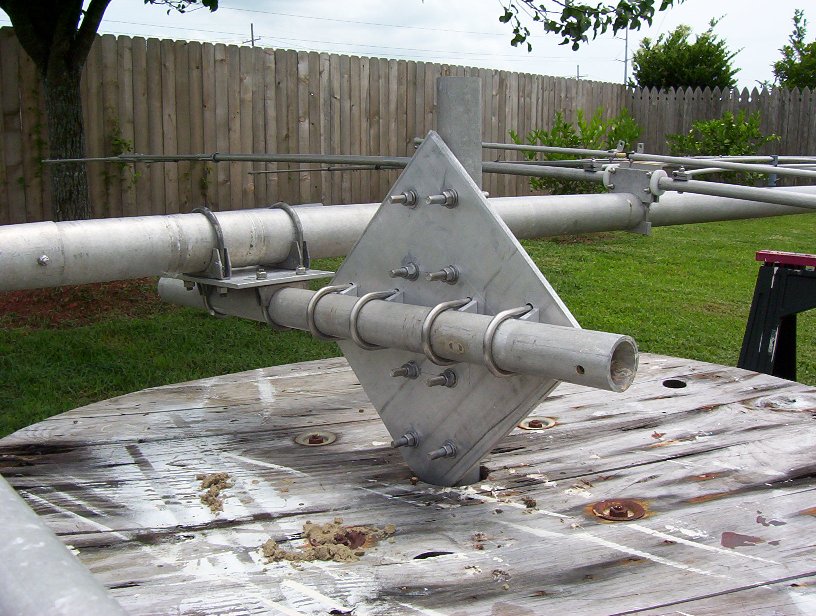
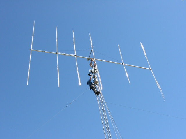
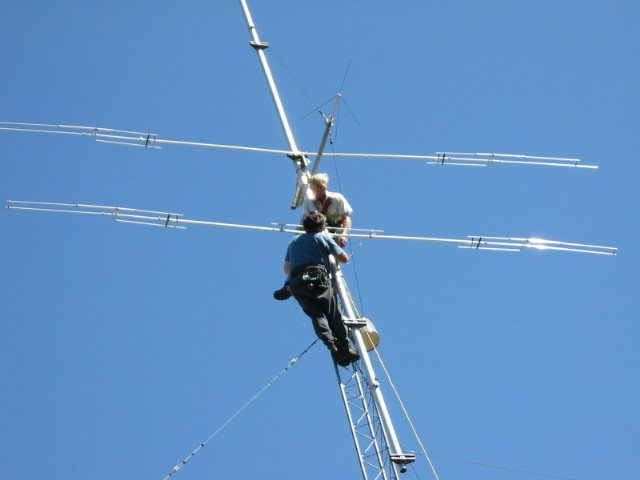
In October 2010, I used this same PVRC mount to install a 3 element SteppIR including the 30/40 meter loop. The first thing was to install the boom onto the PVRC mount so that the boom is vertical alongside the tower. I used my gin pole to raise the boom and place it as close to the horizontal mast as possible (actually just slightly lower). I then lifted the boom slightly by hand, aligned the U-bolts on the boom-to-mast plate with the horizontal mast and slid it onto the horizontal mast. I tightened the nuts on the U-bolts only enough so the boom doesn’t move when pushed slightly.
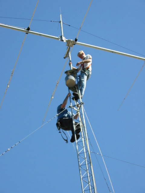
The elements were then ready to be installed. When using a PVRC mount on a guyed tower, you may need to disconnect one of the guy wires when rotating the boom on the horizontal mast. If so, install a temporary guy lower on the tower to support the side you are working on.
I then hoisted one half of the 30/40 meter loop dipole assembly up the tower using the gin pole and installed it, then raised the other half of the loop and installed it. If you are installing a regular-type yagi, such as a KT-36, KT-34, A3S, etc., you would simply raise the entire element and install it on the boom.
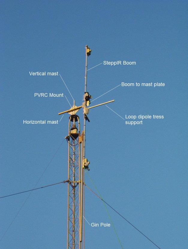
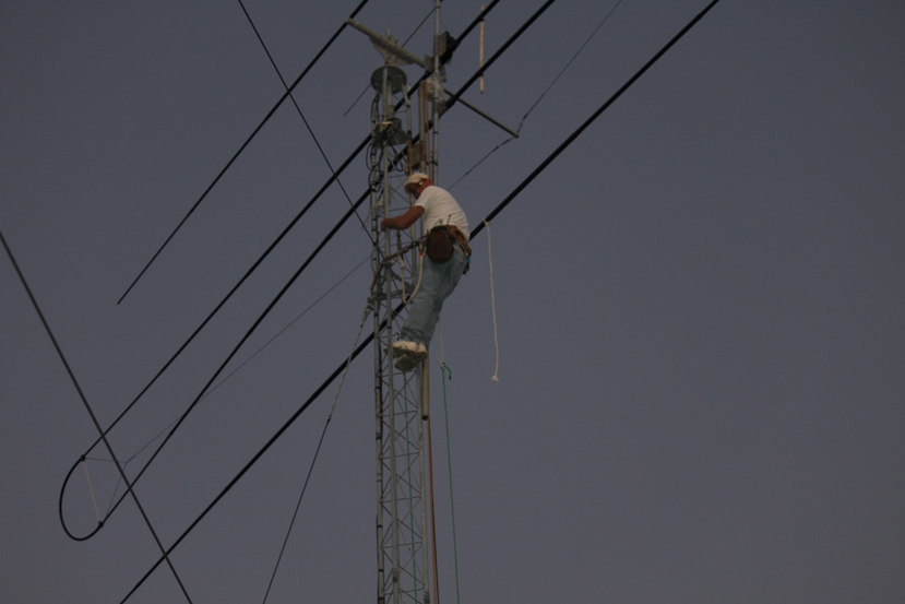
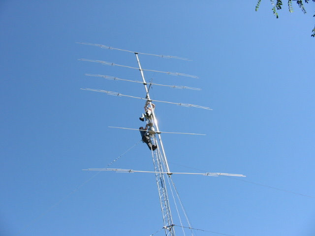
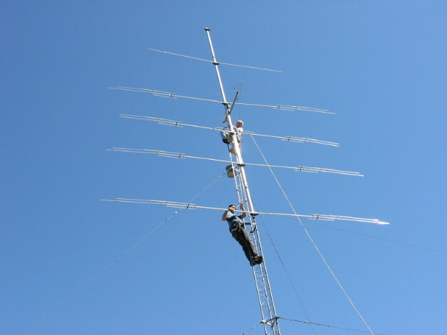
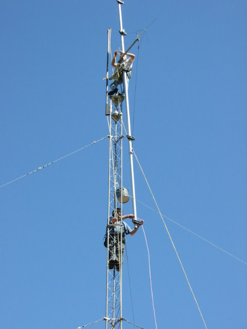
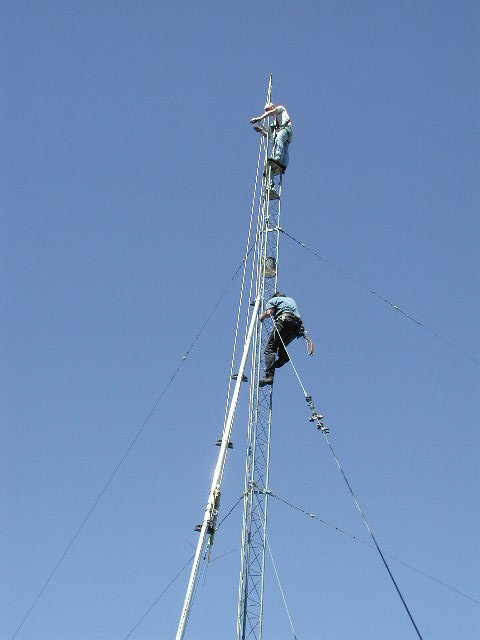
After installing both halves of the loop dipole assemblies, I brought all four fiberglass tubes up the tower. I then stabbed two of the tubes into the lower EHU (reflector) and secured them with the boots and clamps. I then rotated the antenna 180 degrees on the horizontal mast. Next I installed the last two fiberglass tubes into the EHU for the director. I then rotated the entire antenna 90 degrees on the horizontal mast and tightened the bolts. I then loosened the bolts on the SteppIR boom-to-mast plate and rotated the yagi 90 degrees and into it’s final position. Unfortunately I didn’t take any pictures of this but there are more pictures on the SteppIR installation page here. There are excellent pictures of the use of a PVRC mount on another one of my installations in 2012 here. Below is a picture of me on the tower after completing the tape job on the fiberglass tubes for the reflector. As you can see, with the antenna in this position, maintenance or repair of the antenna could be done easily. This is the beauty of installing your antenna on a PVRC mount.
K7ZUM Pictures of a KT36XA and PVRC Mount
Here are some pictures sent to me by Ken, K7ZUM, of a KT36XA antenna that was installed on a PVRC mount. These pictures were taken when the antenna was disassembled and removed from the tower. The antenna would be installed the same way, but just in reverse order. This is a six element tribander on a 36′ boom.
The boom-to-mast plate bolts are loosened and the antenna is rotated 90 degrees so that the elements are vertical instead of horizontal as shown below. The boom-to-mast bolts are then retightened.
The PVRC mount plate-to-horizontal mast bolts are loosened and the boom is rotated 90 degrees on the horizontal mast so that the boom is vertical alongside the tower. The reflector was removed first (lowest element shown below).
The boom was then rotated 180 degrees on the horizontal mast (shown below) so that the first and second director elements could be removed. They were careful to keep the weight evenly distributed along the boom as they removed elements, so they kept rotating the boom and removing elements one-by-one. If you get too much weight above or below the PVRC mount, the antenna is too hard to rotate.
After the first and second director elements were removed, the boom was rotated 180 degrees again (not shown) and the passive element (shown as the top element in picture above without the capacitors) was removed. The boom was rotated 180 degrees again (shown below) and the first driven element was removed (the KT36 has two driven elements). It appears as if they rotated the boom 180 degrees once more to remove the second driven element.
Once the elements were all removed, they removed the boom from the PVRC mount plate and lowered it.
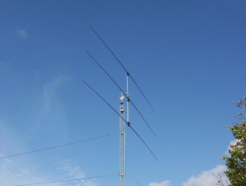
KT34M2 Installation with a Temporary PVRC Mount
In February 2011, I built a small 35′ Rohn 25 tower and installed a KT34 tribander on it using a temporary PVRC mount made from a boom-to-mast plate from a Cushcraft triband yagi. I normally would not use such small gauge aluminum for a PVRC mount, but since the PVRC mount was only used to build the antenna, it worked OK. Once the antenna was built, I removed it off the PVRC mount and installed it permanently to the vertical mast coming out of the top of the tower. The reasons I used a PVRC mount was that 1) I was installing the antenna by myself and 2) because there is a Bradford Pear tree right next to the tower.
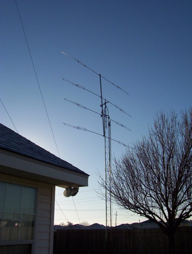
I decided I would install the boom onto the horizontal mast of the PVRC mount with the first driven element already installed on the ground since it was not too heavy or awkward to lift using my gin pole. The top section of the tower is a tapered section. So I installed the PVRC mount plate with horizontal mast onto the tapered section. I set the steel vertical mast into the top of the tower and let it sit in there until the antenna was built. The first driven element was already installed, so the first element installed while on the tower was the second driven element. Once that was installed, I installed the reflector element. I then rotated the antenna 180 degrees and installed the director element and the antenna was completed as shown below. As you can see, I only had to rotate the boom one time in order to complete the installation of the elements.
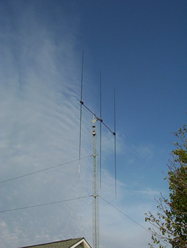
Once the installation of the elements was completed, I rotated the boom 90 degrees so that the boom was horizontal and the elements were vertical (not shown). I then rotated the boom so that both the elements and boom were horizontal. I then attached a rope from my gin pole to the antenna and lifted the entire antenna a few inches off the PVRC mount and onto the vertical mast that was sticking 8″ out of the top of the tapered tower section. I then moved the rope off the boom and tied it to the vertical mast and lifted the mast until the bottom of the mast was up to the bottom of the tapered tower section. I then secured the mast in the tapered section with both a muffler clamp on the mast at the top of the tapered section (to not allow the mast to slide back down) and with a bolt that screwed into the tapered section that pushed against the mast (to not allow the antenna to rotate). I then installed the rotator, lowered the mast down into the mast plates of the rotator and the installation was complete as shown below.
Installing a 3 Element SteppIR with a PVRC Mount in December 2012 – details click here.
Good luck with your PVRC mount installation!
73, Don AA5AU