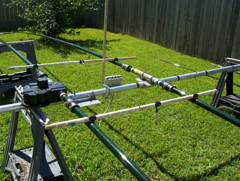
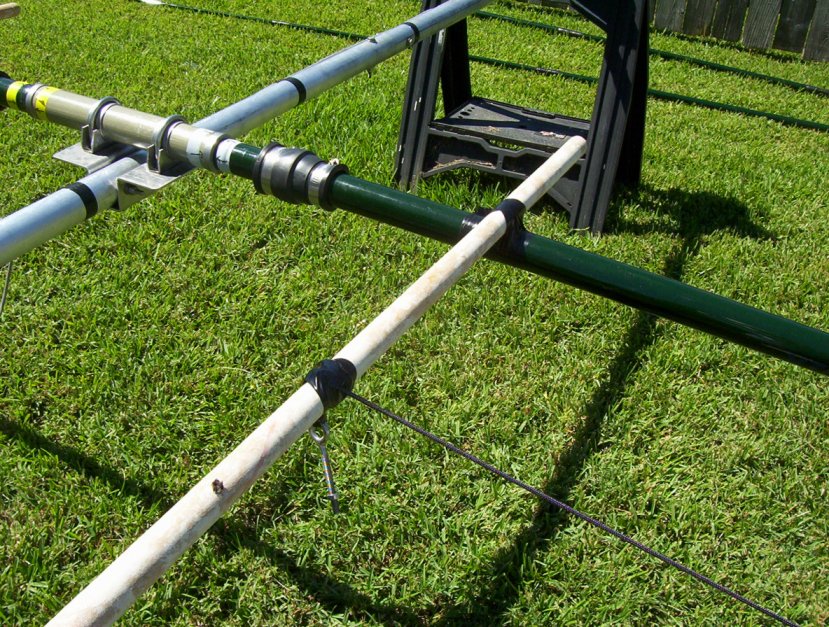
The 30/40 meter “trombone” dipole loop assembly of the 3-element SteppIR can be a challenge if you plan on installing the elements onto the boom after the boom has already been installed on the tower using a PVRC mount. I used a pair of wooden paint roller handles (similar to broom handles, etc). I heavily taped the wooden handles across each of the two fiberglass element poles on each side with the antenna assembled on the ground. The two wooden handles keep the tubes the correct distance apart from each other and allows for easier handling of the elements when on the tower.
And since I installed the tress for the 30/40M dipole loop as well, I taped the Dacron rope to each wooden cross piece so I could easily access them during installation and they wouldn’t be in the way while on the tower.
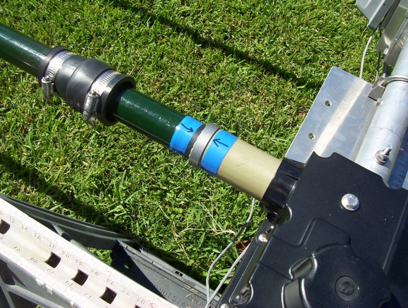
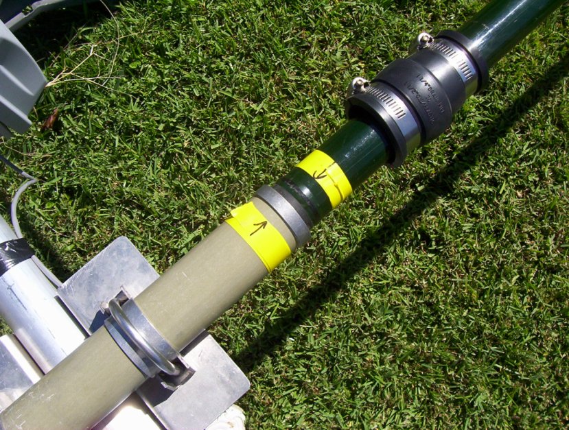
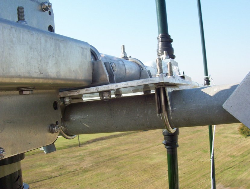
Additionally, I used different colored electrical tape on the ends of each of the element ends and on the EHU and element return cross tube to remind me which pieces fit where. I also made marks on the pieces of tape so the elements would line up correctly. See pictures below.
I first installed the boom onto the horizontal mast of my PVRC mount. I then lifted each dipole loop separately by tying a line to the junction where the wooden pieces were taped to the element that goes into the EST (element support tube) of the EHU (element housing unit – driven). I lifted the dipole loop so that the end of the tube that goes into the EST was just below the opening of the EST (I had taped plastic over the EST openings because the boom was installed the previous day and I didn’t want any moisture to enter the EHU if it rained). My plan was to use the wooden piece to lift the dipole loop by hand and slide it into the EST first, then into the ERT (element return tube). Actually, this was more difficult than I had anticipated. What I ended up doing was stabbing the end that goes into the ERT first (lower on the boom) by using my shoulder as a fulcrum because it was too awkward to lift the entire loop by myself. This would be much easier with two people. Once the return tube of the loop was stabbed into the ERT, and the marks lined up, I removed the colored tape and tightened the boot. I then stabbed the other end of the element into the EHU. I left the wooden poles taped to the loop until the antenna was completed just in case I had to take it down for any reason.
Once the loops were installed into the ESTs, I tightened the clamp over the boot but did not tape it yet. Once the antenna is horizontal, I then adjusted the tubes by twisting them while they were set into the EST and ERT to get any twist out of out the loop. This was very easy to do.
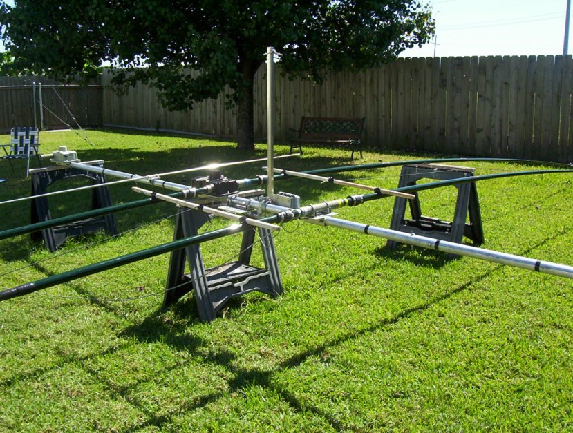
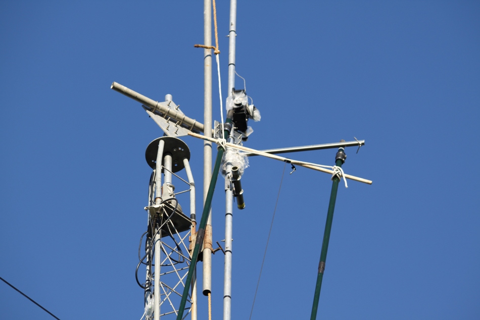
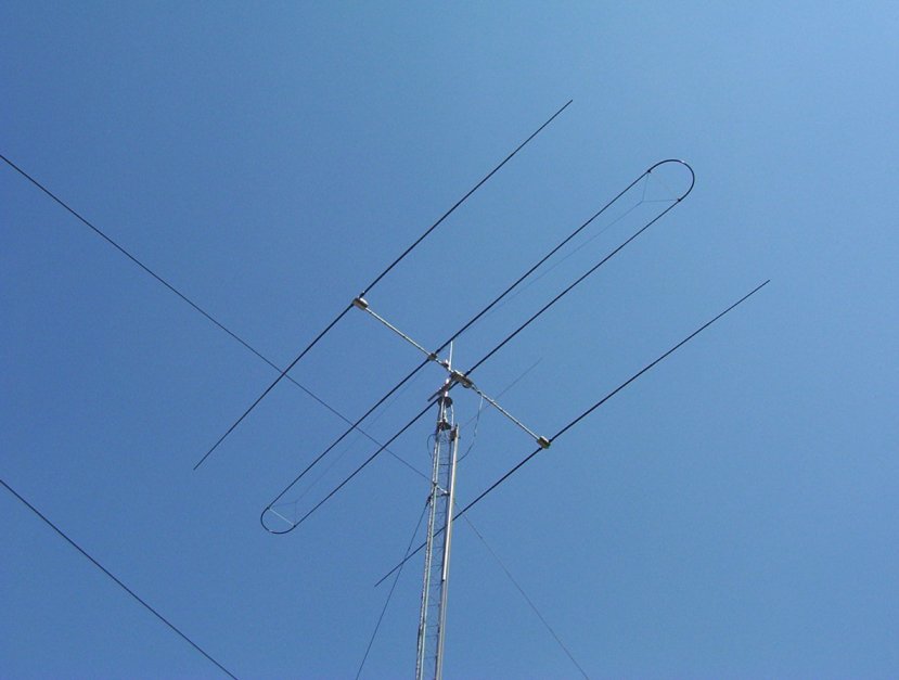
The picture above shows the 30/40 meter loop dipole installed. After the loop dipole was completely installed, the EST was above the ERT on the boom. This put most of the weight of the element below the top of the tower. Instead of installing the director tubing at this point, I went ahead and rotated the boom 180 degrees by loosening the U-bolts holding the boom-to-mast plate on the horizontal mast of the PVRC mount, then rotating the boom by hand, so the EHU is below the ERT. I then installed the director tubes. This was quite easy since they are light weight and easy to handle. After I installed the director tubes, I put on the boots, tightened and taped them. I then rotated the boom 180 degrees again and installed the reflector tubes. I installed the boots, tightened and taped them with both electrical tape and silicone tape (purchased from Home Depot). In the picture below, I’m finishing taping the director tubes.
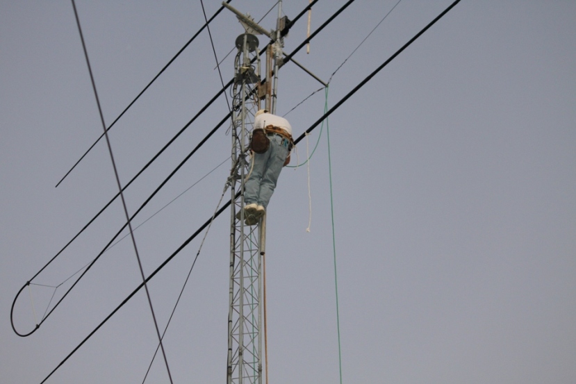
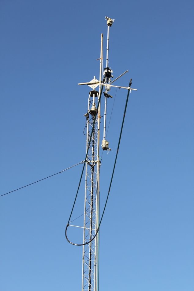
At this point, you then rotate the boom on the horizontal mast 90 degrees so that the boom-to-mast plate is horizontal and on top of the horizontal mast of the PVRC mount. I don’t have a picture of this other than from the tower (next picture). I then tightened the U-bolts that holds the boom-to-mast plate onto the horizontal mast. I then loosened the U-bolts holding the boom to the boom-to-mast plate and rotated the boom 90 degrees into its final position. After tightening the U-bolts that hold the boom to the boom-to-mast plate, I then loosened the boots on the EST of the EHU and ERT (do not remove the boots, only loosen the clamps holding the boots to the tubes) and adjusted the trombone element so there was no twist in it. I then went down the tower to look at the loop to make sure it was not twisted. It was not. I climbed back up the tower, tightened the clamps on the boots, taped it with electrical tape and silicone tape.
I know I said I did not tape the tubes of the trombone element until the antenna was horizontal, but I screwed up. This picture shows them taped because it was dark when I turned the antenna to it’s final position the evening before. The next morning I looked up to see a small piece of white rope (used to tie the tube to the tower) still tied to the reflector tube as shown above! So I had to turn the antenna vertical again, then swing it 90 degrees so I could remove the white rope. Had it not been for the PVRC mount, I would have had to live with a small piece of white rope hanging from my new antenna.
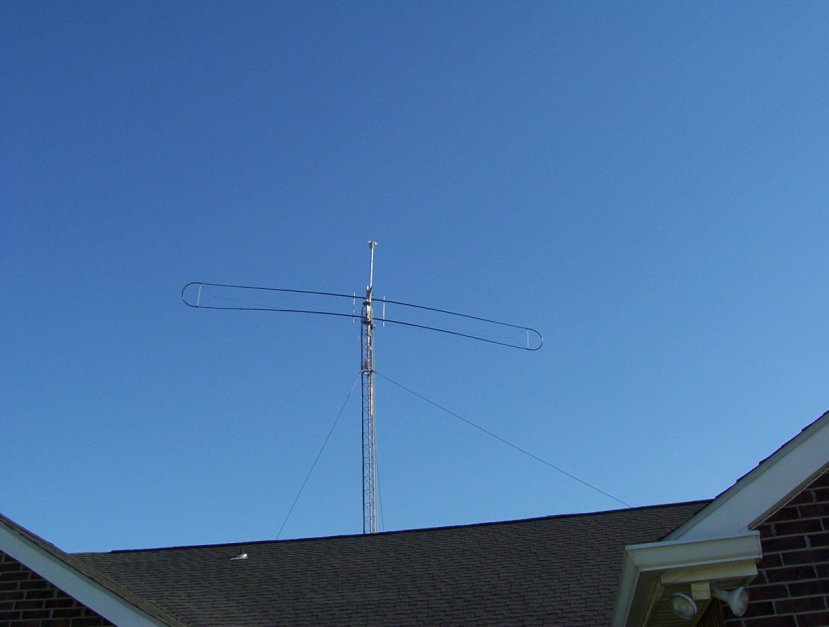
This is what it looked like when completed.
At the time I finished this page, the antenna had been on the air for six months. I can only say it’s the best damn antenna I’ve ever owned. I could write an entire page on how great this antenna is, but I won’t. You have to trust me. It works very well. I may not like it if it ever breaks, but I sure love it now.
73, Don AA5AU