Troubleshooting High SWR on 3-element SteppIR Yagi Antenna
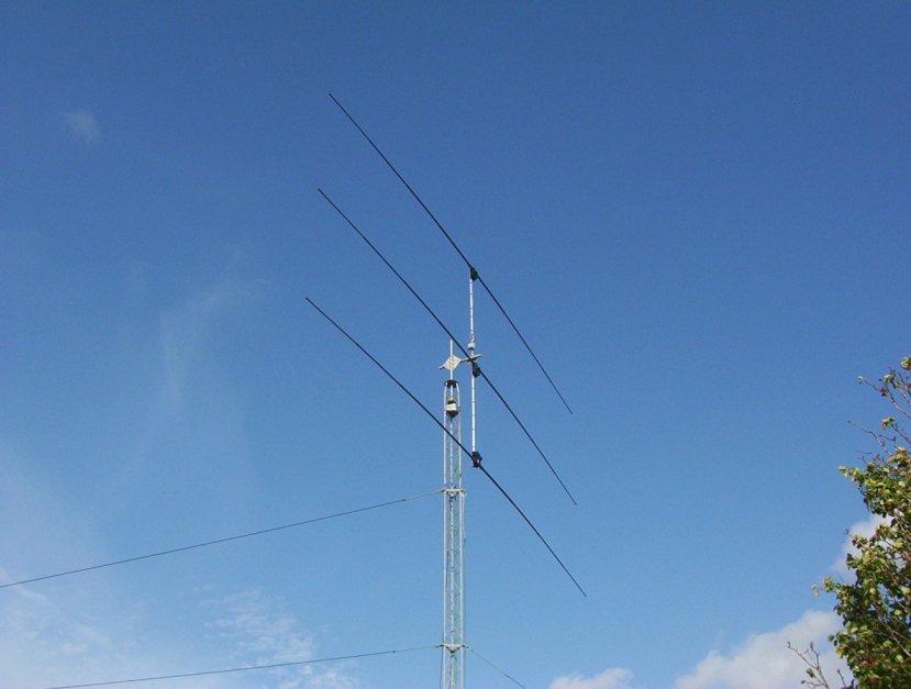
On Sunday morning November 1, 2015, I noticed higher-than-normal VSWR while using my 3-element SteppIR on 15 meter JT65. The SWR was around 2:1 when it is normally flat (1:1). I had used the antenna the previous day with no issues. The only significant thing going on was that it had started raining Saturday night and was raining heavily on Sunday. However, rain is nothing new in Louisiana and the antenna had performed perfectly since it was installed in December 2012, nearly 3 years ago.
I started troubleshooting by eliminating everything in the antenna line (bandpass filter, amplifier) and performed SWR graphs on 10, 12, 15, 17 and 20 meters in both the forward and 180 degree positions and on 6 meters in the forward position only (180 does not work on 6 meters). I made the measurements directly on the coaxial cable connected to the antenna and entered them into a spreadsheet.
I also checked the lengths of each element and entered them into the table below. These measurements are not necessarily default values for the antenna but they are probably very close to default.
| AA5AU 3-Element SteppIR Element Lengths 11/1/2015 | |||||
| Band | Frequency | Director | Driver | Reflector | SWR |
| 6M | 50100 kHz | 101.8″ | 111.2″ | 115.4″ | 1.7 |
| 10M | 28050 kHz Forward | 184.6″ | 191.9″ | 196.8″ | 1.8 |
| 28050 kHz 180 | 199.8″ | 191.0″ | 182.4″ | 2.0 | |
| 12M | 24900 kHz | 208.2″ | 218.0″ | 225.6″ | 1.5 |
| 24900 kHz 180 | 225.6″ | 216.7″ | 207.9″ | 1.3 | |
| 15M | 21050 kHz Forward | 247.7″ | 260.9″ | 267.8″ | 2.1 |
| 21050 kHz 180 | 268.6″ | 259.5″ | 243.1″ | 1.5 | |
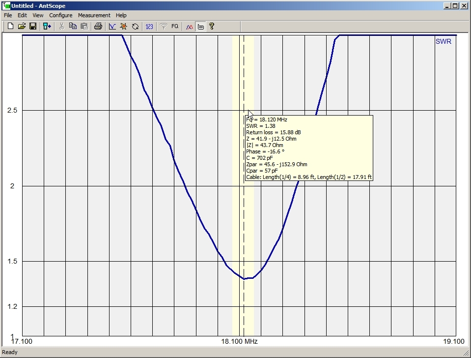
| 17M | 18070 kHz Forward | 294.3″ | 306.3″ | 323.1″ | 2.5 |
| 18070 kHz 180 | 321.0″ | 304.4″ | 291.8″ | 1.5 | |
| 20M | 14050 kHz Forward | 383.5″ | 399.3″ | 414.4″ | 2.8 |
| 14050 kHz 180 | 412.9″ | 398.1″ | 380.9″ | 1.1 | |
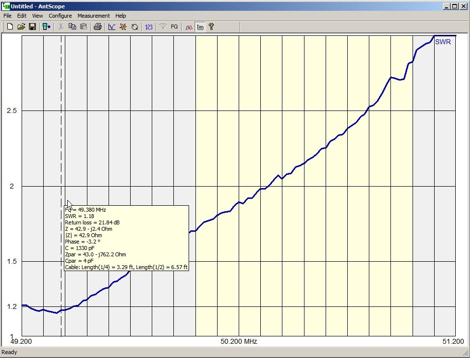
I used my RigExpert AA-54 antenna analyzer and AntScope software to plot the SWR into graphs so I could get a visual idea of what might be wrong.
6 Meters Forward Mode – Antenna set to 50.2 MHz – Resonance near 49.38 MHz
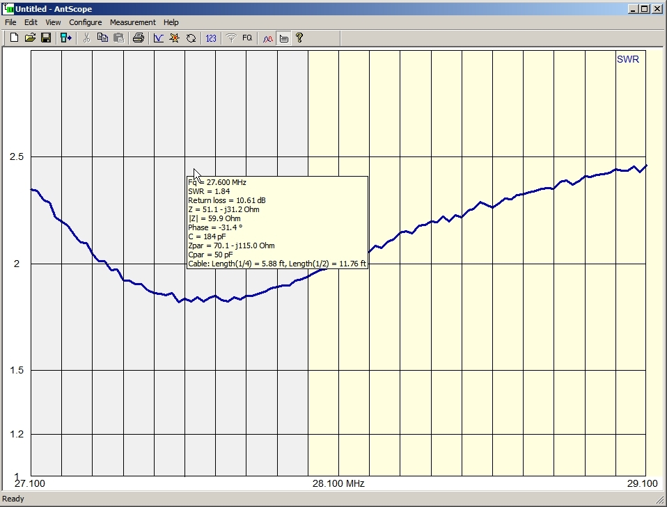
10 Meters Forward Mode – Antenna set to 28.1 MHz – Resonance near 27.6 MHz
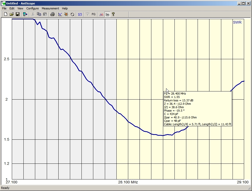
10 Meters 180 Mode – Antenna set to 28.1 MHz – Resonance near 28.4 MHz
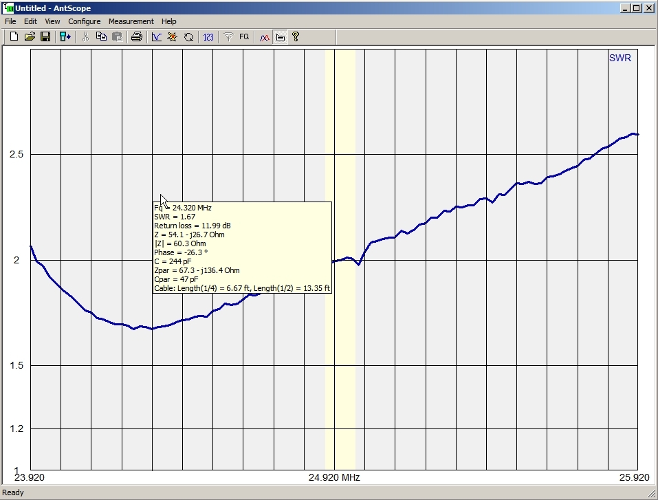
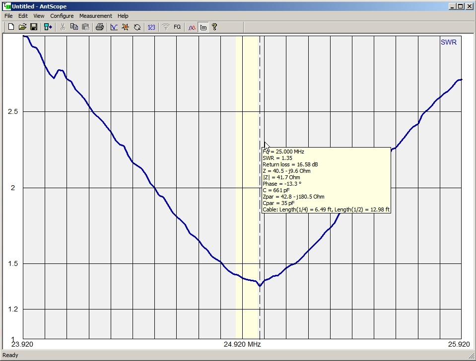
12 Meters Forward Mode – Antenna set to 24.92 MHz – Resonance near 24.32 MHz
12 Meters 180 Mode – Antenna set to 24.92 MHz – Resonance near 15.0 MHz
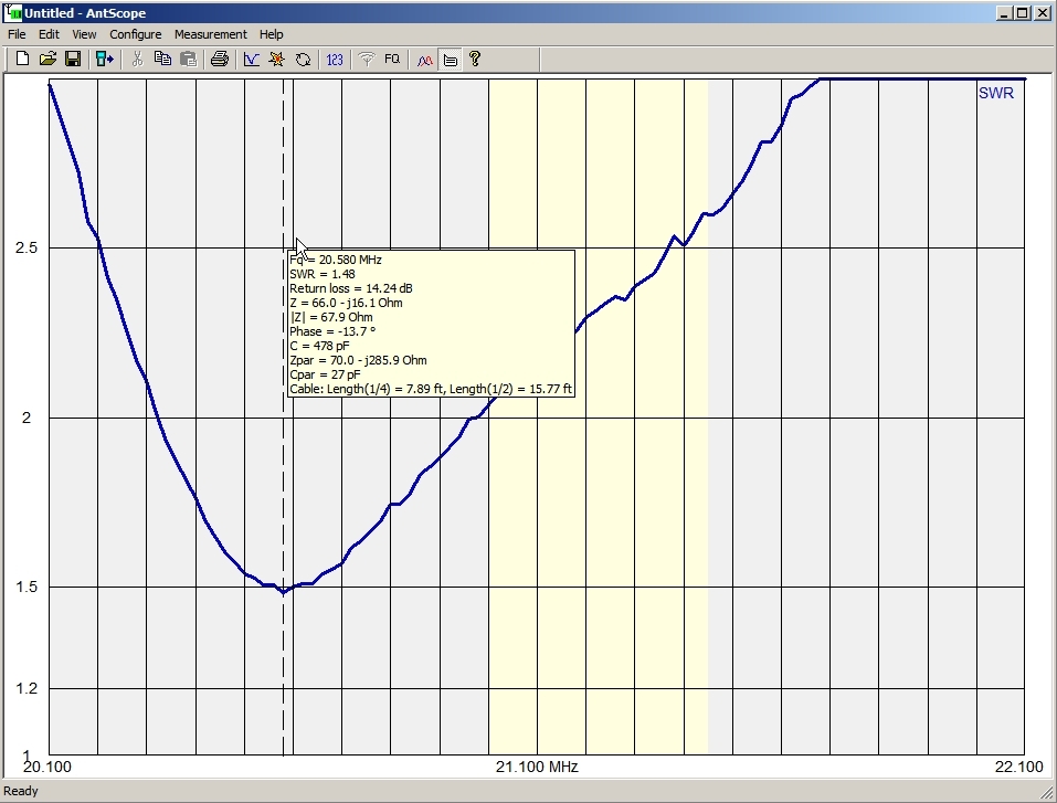
15 Meters Forward Mode – Antenna set to 21.1 MHz – Resonance near 20.58 MHz
15 Meters 180 Mode – Antenna set to 21.1 MHz – Resonance near
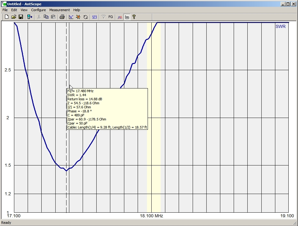
17 Meters Forward Mode – Antenna set to 18.1 MHz – Resonance near 17.48 MHz
17 Meters 180 Mode – Antenna set to 18.1 MHz – Resonance near
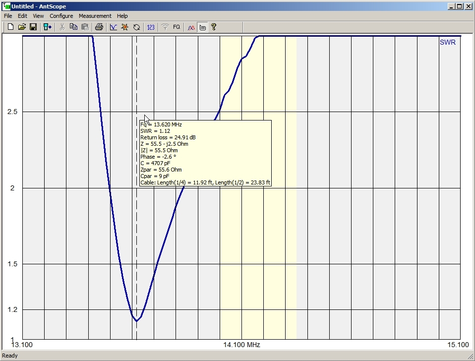
20 Meters Forward Mode – Antenna set to 14.1 MHz – Resonance near 13.62 MHz
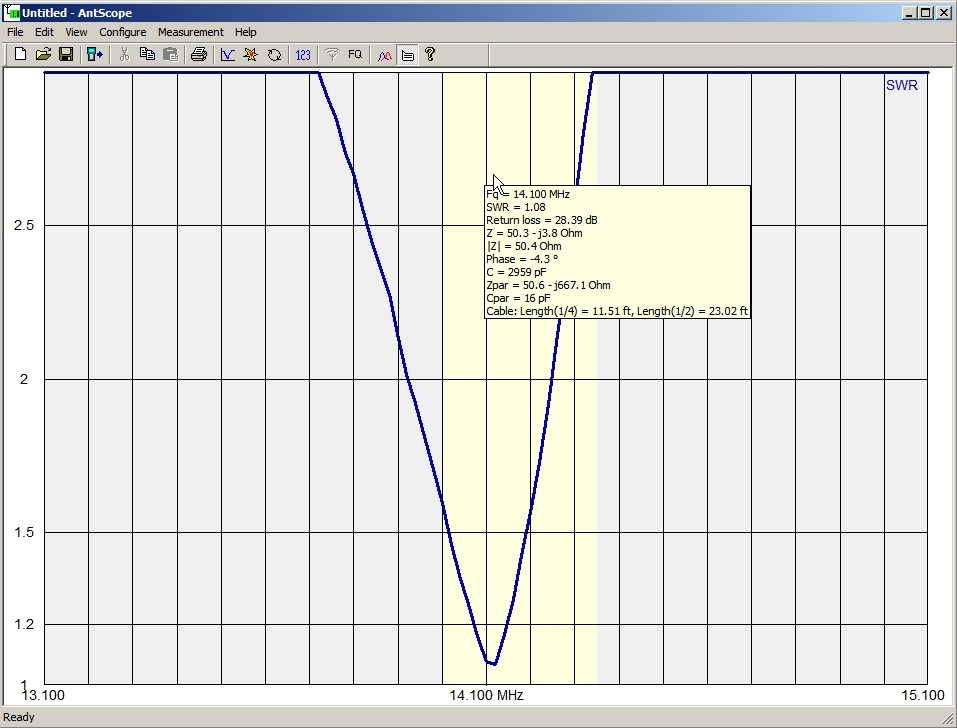
20 Meters 180 Mode – Antenna set to 14.1 MHz – Resonance near
[wpanchor id=”bypass”]
Looking at the SWR graphs did not give me any immediate indication of what could be wrong. I downloaded all the troubleshooting guides on the SteppIR website and read through each one. From what I read, SteppIR suggests that if one of the passive elements is not working then you can get higher-than-normal SWR (up to but not more than 3:1) and normal readings are possible on some bands or in the 180 mode. This is exactly what I see in the graphs. I’m thinking I have a passive element not working.
SteppIR suggests testing the voltage output of the controller so I did. The voltages checked good on all outputs to the motors which is 3 VDC when idle and 24 VAC when active . Next I checked the resistance on the cable going to each motor winding with the connector disconnected from the controller. The Driver and Director windings checked good as did the first winding (pins 9 & 10) of the Reflector. However, the second winding of the Reflector motor (pins 11 & 12) measured 100 ohms which seems high. I decided to climb the tower the next evening after work.
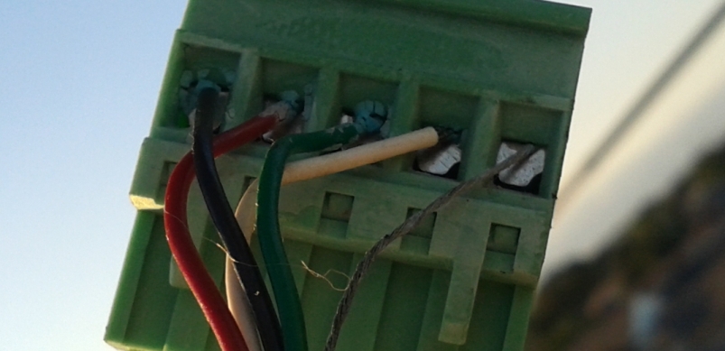
Before going up the tower, I measured the resistance of pins 11 & 12. I didn’t write it down but I believe it was around 200 ohms. When I opened the connector box up on the tower, I was surprised to see there was very little, if any, corrosion (see photo below of one of the connectors). What you see in the photo is not corrosion. It’s the connector gel after hardening.
I measured the resistance of each winding at both the connector from the shack and on the connectors going out to the EHUs (element housing units). All measured between 15 and 17 ohms which is normal. So where was I getting the 100 ohms from? I measured the resistance of the each pair going back down the cable to the shack. The cable pairs all measured open. Did I somehow clear the high resistance problem and not know it?
While on the tower I decided to go ahead and remove each wire from all 4 connectors, cleaning any corrosion, and re-applying connector grease. I then remeasured each winding. They were all 15-17 ohms EXCEPT the second winding going to the Reflector which measured 25 ohms (this is the suspect pair/winding). I removed the green and white wires from the connector and remeasured directly on the wires going out to the EHU. It was still 25 ohms. Something seemed not right but I thought to myself that 25 ohms is better than 200 ohms so I re-installed all the connectors and came down the tower as I was losing daylight.
Inside the shack I measured pins 11 & 12 to find it measured 2600 ohms. Why the change? I remeasured 11 & 12 again a second time and now it was 2800 ohms. I few minutes later it was 2500 ohms, then 2900 ohms and finally 3000 ohms. Suspecting a bad meter or meter leads, I went and got my work meter out of the truck. Both meters measured the same at 3000 ohms. I took the outside case off the connector and resoldered the wires on pins 11 & 12 to eliminate any possibility of a cold solder joint and placed clip leads directly where the wires are soldered onto the connector. It read 326 ohms with both meters. I left everything as it was and went to the bed disgusted I hadn’t really gotten anywhere with this problem. The next morning it was still 326 ohms. But later than evening it was 69 ohms. This was strange.
I went back up the tower and remeasured everything the next evening. I had put a short on the pair going to pins 11 & 12 in the shack and measure the pair (Rose/Creme) at 3 ohms at the connector box. With the short removed (thanks to the XYL), the cable measured open.
I then checked the resistance across the suspect reflector winding and it was more than 2000 ohms across the green/white pair of the cable going to the Reflector EHU, I watched as the reading fluctuated. I did the same to the black/red pair and it showed 17 ohms and was steady. Back to the green/white pair and it was fluctuating. I then cut a couple inches off the end of the cable, stripped back the jacket and insulation and saw that the cable was clean as new. I measured the green/white pair and again it was fluctuating and measured over 2k ohms. A visual inspection of the cable from the connector box to the Reflector EHU looked good with no damage.
At this point, I drew two conclusions. The cable from the shack to the connector box is good. The problem is in the Reflector EHU. However, my next test would prove the problem was NOT in the Reflector EHU. Back in the shack, I used Create/Modify to move the Reflector tape to different lengths and to my surprise, the SWR plots changed on every band. Moving the Reflector was changing the RF characteristics of the antenna which means the Reflector tape was moving! I did the same to the Director tape and was surprised to see there was no change to the SWR plots when the Director length was changed with Create/Modify. This was very confusing. At first I thought perhaps I accidentally swapped the Director and Reflector connectors in the connector box. I knew I hadn’t because I only had one connector disconnected at any time. To double check this, I climbed the tower again to confirm the connectors were correct and they were.
Now I was convinced the problem was in the Director EHU even though the Reflector EHU had strange resistance reading on the motor. I was convinced the Reflector tape was definitely moving because I was able to adjust the antenna for low SWR (near 1.2:1) on 10, 15 and 20 meters and used the antenna at the start of CW Sweepstakes that Saturday. The plan would be to remove the Reflector EHU and fiberglass tubes on Sunday 11/8/2015. A cold front moved through on Friday night/Saturday morning and it rained all day Saturday. Because the antenna is installed on a PVRC mount, removing the EHU was not a major job although it was a bit more dicey considering the windy conditions. When boom is positioned alongside the tower (as in the Photo B), there is easy access to the EHU. Photo B was actually taken during the installation back in December 2012 but it shows the ingenious idea of the PVRC mount. Unfortunately the weather would not be as calm as when Photo B was taken.
The rain finally stopped around 9 AM Sunday morning. By 10 AM, the tower was dry but the wind was starting to blow pretty good. I climbed the tower and removed the Reflector EHU with the fiberglass tubes still installed. I did this because I didn’t know if there was any tape left inside the tubes. Plus with the high wind that morning, I wanted to get the job done quickly and get off the tower. Had the weather been calm, I might have removed the Reflector EHU as well in order to try to figure out the high resistance of the 2nd winding to the motor. But not this day.
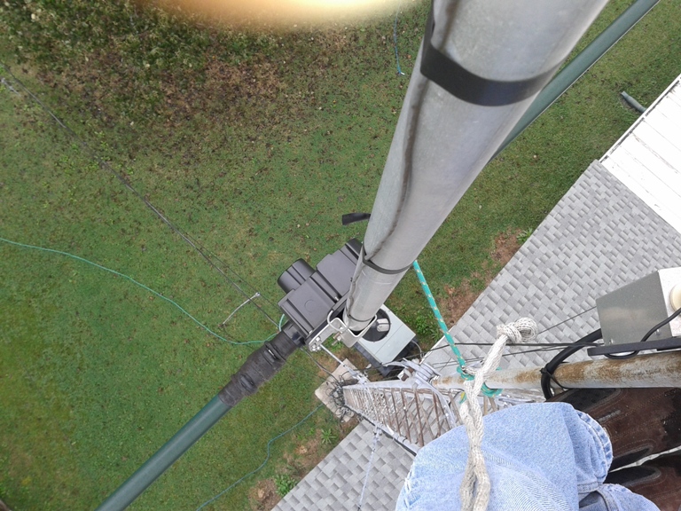
Photo C was taken looking down the tower at the suspect Director EHU. Notice that I tape over the rubber boots to keep them from dry rotting.
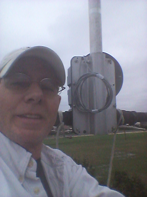
I couldn’t help but take a selfie next to the suspect Director EHU. The hardest part of the job was removing the seven screws and nuts holding the EHU to the aluminum plate on the boom without dropping anything or having my hat fly off in the wind. Photo D shows two ends of a rope bridle tied to each fiberglass tube at the rubber boot. The bridle was tied to a metal ring clip. The rope I used to lower the EHU was also tied to the ring clip and the ring clip was clipped onto the tower so the whole thing would not drop when I removed the last screw. I was a little worried about losing that last screw or nut because the wind was blowing so hard, the EHU was separating from the aluminum plate as I was loosening it. I knew I could always get more screws and nuts, but I just hate losing anything.
I thought to myself “I wish this wind would stop for a second so I could get this damn thing off”. Well, wouldn’t you know it? The wind stopped. I couldn’t believe it but I didn’t waste any time getting that last screw out without it falling to the ground! I quickly lowered the whole thing down before the wind kicked up again. Man, what a break!
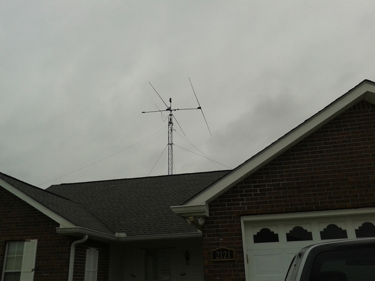
I went ahead and brought the antenna back to it’s normal position on the tower. Sure looks strange though.
On the ground I set the EHU on a work table and removed the lid. I wasn’t real happy when I saw the tape had come off the spools inside the EHU (Photo F). I was correct in assuming the problem was in the Director EHU. Here’s the proof.
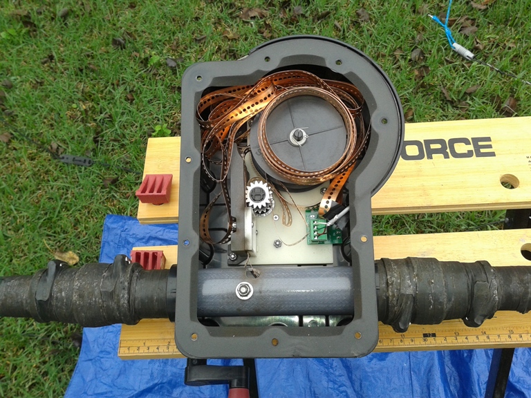
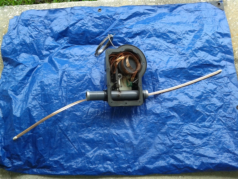
I then removed the fiberglass tubes. I put the plugs in the ends of the tubes to keep rain and insects out and stored them on the side of the house. As you can see in Photo G, there was about 16″ of tape sticking out from each side of the EHU.
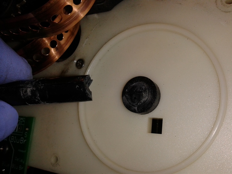
When I got the EHU on my work bench in the shack, I did a visual inspection but didn’t immediately see signs of anything broken. I removed the bullets from the ends of the copper tape and removed the three screws holding the inside assembly. When I turned the EHU over to remove the three screws from the housing, the two spools fell out of the EHU on their own. When I turned the housing back over I could see where the shaft supporting the spools had broken off near the mounting plastic plate. It was this broken shaft which caused the tapes to unwind inside the EHU.
Instead of waiting for parts from SteppIR, I decided to use parts from a 2010 EHU that was damaged in a hurricane in 2012. See that refit page here.