Winds from Hurricane Isaac in late August 2012 severely damaged my 2-year old 3-element SteppIR with 30/40 loop dipole that was on my 55′ tower. After some close examination, I had an idea that it could possibly be rebuilt back to it’s original state but it would take some work and I needed parts. But because of the damage caused by a “minimal” hurricane, if there is such a thing, I decided not to put a 3 element with 30/40 loop back on the taller tower. The difference in wind speed at 55′ compared to 35′ is substantial. My KT34M2, which was installed on a separate tower 35′ tower, did not appear damaged at all but did have high SWR on 20 meters after the storm so it needed to come down. Since only one of the three EHU’s on the SteppIR was physically damaged, I decided to go ahead and build a 2-element version of the SteppIR in order to get back on the air. I would install it on the 35′ tower because the 55′ tower needs some sections replaced due to a slight bend caused by the storm.
In early October 2012, I started working on building the 2-element version of the SteppIR. On suggestions from two people on the SteppIR email reflector, I decided to use 72″ separation of the two elements instead of the standard 57″ inch separation. I was told that I would get more gain out of the antenna. I don’t have antenna software in which to model the antenna with 72″ inch separation, so I went ahead and trusted the sources. For a boom, I used one half of the 3 element boom. The standard 3-element boom is comprised of four 4′ pieces. So I took the boom apart in the middle and used half of it for the new antenna. The whole idea was to not do anything that would impair me from rebuilding the antenna back to 3-elements in the future. So using half the 16′ boom made sense. I left the driven EHU in place and moved the reflector EHU bracket and return tube brackets to the appropriate locations and drilled new holes into the boom for the brackets. I mounted everything on the boom and did a motor test. Both the driven and director EHU’s passed the motor test.
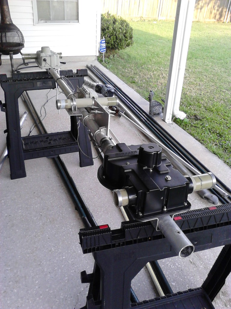
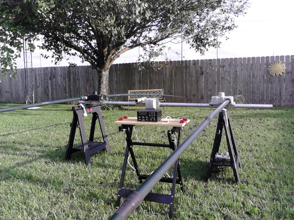
Once the motors were tested using TEST MOTORS in the controller, it was time to see if they were working to the point of pushing the tape through the tubes, so I built the antenna on sawhorses in the backyard and tested again. Everything seemed to be working fine. And I did remember to disable the 40M option in the controller first so I would not accidentally go to 40 meters and push the tape out the ends of the tubes! (Note the location of the boom-to-mast bracket in the above picture. It is located too far back toward the driven EHU. I had to slide the boom back in order to balance the antenna when it was installed on the tower.)
The next step was to remove the KT34 off the tower. Since the antenna was not mounted on a PVRC mount, this proved a little tougher than expected for one person on the tower, but I got it down safely with no damage. It was a lot of work because I had installed the antenna five feet above the top of the tower. I had to remove the rotor, lower the mast into the tower, clamp it, pull the two driven elements, unbolt the boom, swing the boom into the tower to remove the reflector and director elements, then lower the boom, remove the mast, re-install the rotor and re-install the mast. This took two days by myself. I decided I would install the new antenna directly above the top of the tower to make things easier for me on the tower.
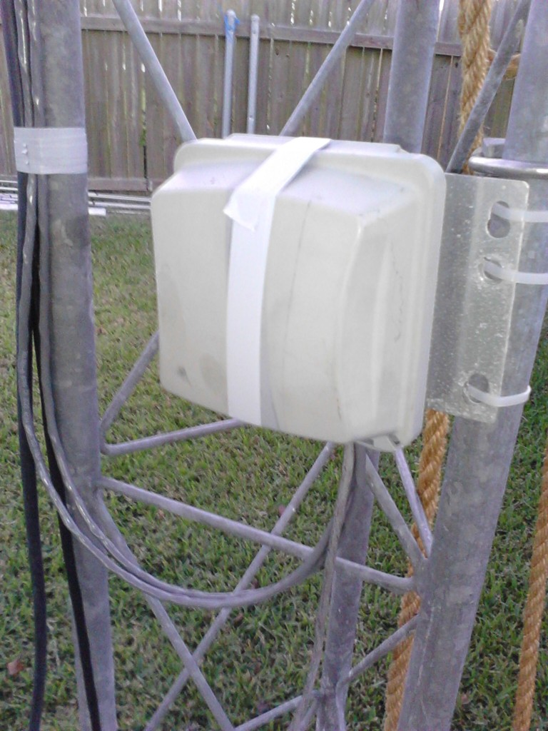
The 12-conductor control cable coming from the controller in the shack would not reach the antenna on the 35′ tower that is located at the rear of the backyard. I didn’t have 12-conductor shielded cable at hand. I had ordered new control cable along with parts to repair the 30/40 loop dipole but I didn’t expect them to arrive anytime soon and they didn’t arrive by the time the antenna was installed on the tower. I started installing the antenna on the tower on Thursday 10/18/12 and finished the next day. While laying in bed Friday night I got the idea to mount the connector box at the base of the tower instead of on the boom, then use two runs of 4-conductor shielded cable up the tower and splice them to the existing 4-conductor cable coming from the two EHU’s. I had new 4-conductor shielded cable in the garage. So Saturday 10/20/12, I did just that along with running brand new RG-214 and new coax connectors. I took my time to do a “permanent” installation because I was thinking that I had to use this antenna as my primary antenna while waiting for my new 3-element SteppIR to come sometime in December. Plus if the darn thing worked, I just might leave it 2 elements. (Editor’s note: It did work and it worked great. It’s still up there and I’ve made hundreds of contacts using it on a second radio in RTTY contests.)
I finished the job around 3 PM (2000Z) Saturday. The JARTS WW RTTY Contest was going on that weekend. Being an avid RTTY contester, I was eager to jump in to see how the antenna worked. I checked in the RTTY portion of the band on 10, 15 and 20 and was very surprised to see SWR of 1.5:1 or less on each of these bands using the existing 3-element settings in the controller. So I went ahead and started contesting. I ran barefoot as much as possible to see the capabilities of the antenna. I have to tell you I was blown away by the performance. Then again, the SFI was over 150 with low A and K indexes. With conditions this good, I would expect anything to work. I did have to turn the amp on to work BD3CB on 15 meters, but other than that, I had no problems working Japan and other Asian stations with 100 watts.
After 10 and 15 meters went away a couple hours after sunset, I took my RigExpert AA-54 antenna analyzer and started tweaking the antenna. With no antenna software, I decided to go ahead and set the antenna for lowest SWR and resonance at a known starting point in each band using CREATE/MODIFY in the controller. I started with the 3-element setting and ran a graph using the AA-54 analyzer and its AntScope program to find where it was resonant. I adjusted both elements alternately until I achieved the lowest SWR and resonance at my starting point on each band, which was 28100, 21100 and 14100 kHz (I would tweak 12 and 17 later). Once I was happy with the measurements on a particular band, I ran CALIBRATE on the controller and checked up the band, running graphs at various frequencies to ensure lowest SWR and resonance at each chosen frequency. It all worked extremely well. Once I was finished with the NORMAL direction, I did the same for 180 mode. All this took several hours and I didn’t get to bed until 2 AM. I understand that lowest SWR doesn’t always translate to maximum gain but it was good enough for me. I love 1:1 SWR! See the graphs for 10, 15 & 20 meters here.
The next morning I had great runs into EU on 10 and 15 meter RTTY in the JARTS contest running barefoot. I was amazed at how well the antenna performed. It performed much like it did as a 3 element at 55′ with the biggest difference being poor front-to-back and hearing strong signals off the side which is not necessarily a bad thing in a contest. This is understandable considering it’s only 2 elements at 35′. Because of these qualities, I may keep it as 2 elements even after I get the new 3 element up. This antenna will primarily be used on a 2nd radio during contests anyway. Then again, 3 elements is always better than two. Who knows? I have time to think about it.
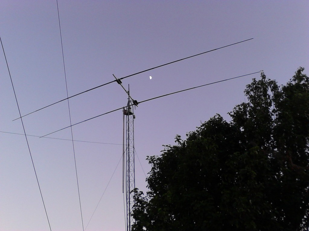
I plan on adding the 30/40 loop when parts come in from SteppIR. This will require removing the 2 fiberglass poles on the driven EHU, adding the loop return tube and then installing the “trombone” on each side. Shouldn’t be a huge job but nothing is really ever easy with only one person on the tower. I’ll update this page once the loop is installed. This is what the antenna looked like on October 22, 2012. I ended up with nearly 500 contacts in the contest in a casual effort for 14 hours. Not too shabby.
73, Don AA5AU