On November 1, 2020 (Sunday)
In preparation for Hurricane Zeta in late October 2020, I removed the fiberglass poles from both 3-element SteppIR yagi antennas in order to lessen the wind load on the towers. One yagi (2012 model) is on a 45′ tower and the other (2010 model) is on a 35′ tower. Before doing this I performed SWR checks on various bands and noted that something wasn’t right with the antenna on the lower tower (2010 model). The SWR was less than 3:1 on all bands but it was higher than normal. This antenna is only used for contesting and sat up unused for most of 2020. Luckily both towers survived the strong Category 2 storm when it came ashore in southeast Louisiana on Wednesday, October 29th. The eye passed directly over my QTH at evening. It is the first time I had ever been in the eye of a hurricane. The storm was frightening but the calmness of the eye was surreal.
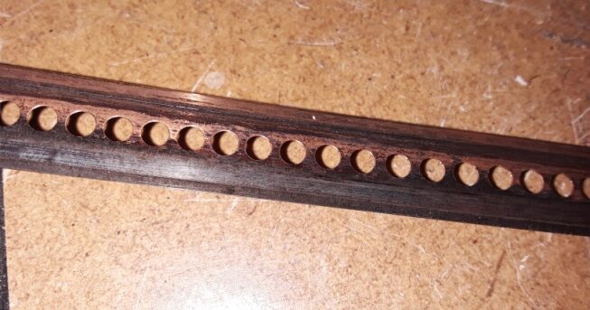
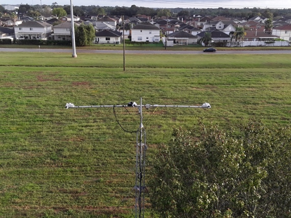 3-element SteppIR yagi at 35′ with poles removed before Hurricane Zeta October 2020
After the storm, I put the poles back on both antennas and did SWR checks. The main SteppIR at 45′ was good but the lower antenna was showing about 2:1 SWR or higher on all bands. I know from experience that this usually means that either the director or reflector wasn’t functioning. To find out which element wasn’t moving, I used the Create/Modify function in the SDA-100 controller to move the tapes for each element to see if the SWR graph changed on my RigExpert AA-54 antenna analyzer.
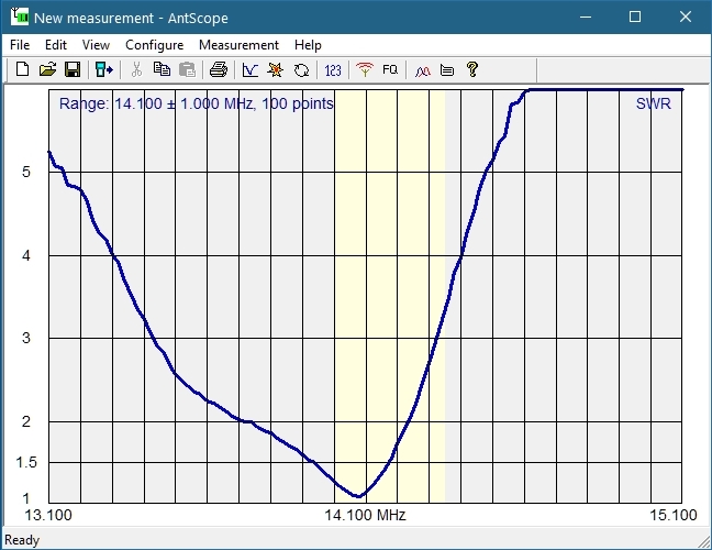
Below is the graph when tested on 15 meters in Normal mode. I moved the director first and there was no change in the curve so I knew the director wasn’t moving. I then tested the reflector and to my surprise, it didn’t change the curve either – it looked identical to the graph shown below. It was apparent it wasn’t working either. I was confident the driven element was moving or else I wouldn’t be getting dips on each band but I tested it anyway. The driven element was working.
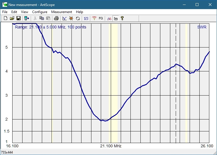 Graph for 15 meters showing higher than normal SWR
I checked the resistance on each motor at the controller end of the control cable. The resistance was good for each motor which suggested the cable was good all the way to each EHU (element housing unit). Each motor showed 22 ohms of resistance and they were all the same. I also tested each conductor to ground and found no shorts.
I next tested the voltage on pins 1 & 2, 3 & 4 (driven element), 5 & 6, 7 & 8 (director), and 9 & 10, 11 & 12 (reflector) both idle and when running and the voltages were good (2 volts DC idle, 24 AC running). This suggested the controller was good. It was pretty clear to me both the director and reflector were not moving and the antenna was broken.
November 2, 2020 (Monday)
When I got home from work I climbed the tower and rotated the antenna on the PVRC mount so the boom was alongside the tower and the director EHU was accessible. It was starting to get dark and so I left the antenna in this position. A big cold front had blown in so no rain was expected for several days.
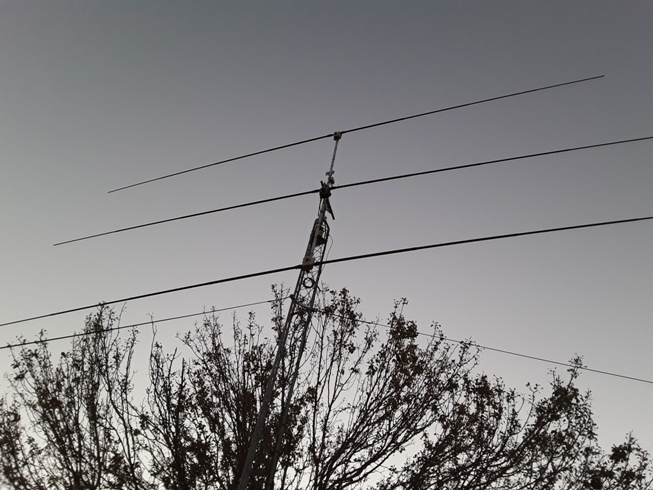 Antenna rotated on PVRC mount with boom alongside tower
November 3, 2020 (Tuesday)
After work I removed the director EHU off the boom. The one thing I didn’t expect was the swarm of mosquitos that showed up! I knew something was broke when I heard something rattling inside. I opened the EHU and discovered the sprocket shaft had broken where it attaches to the stepper motor.
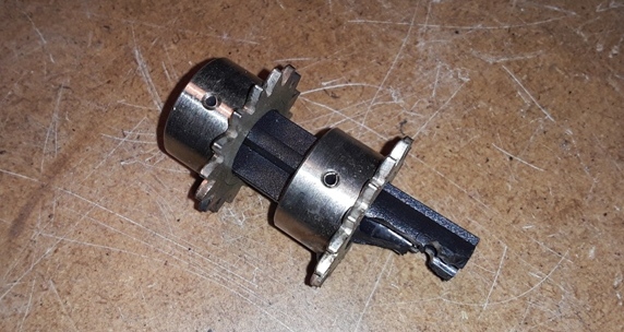
Broken sprocket shaft out of director EHU
November 4, 2020 (Wednesday)
After work I removed the reflector EHU off the antenna while again fending off pesky mosquitos. I then rotated the antenna back its normal position.
There were no parts rattling inside. When I opened it up on the bench, everything was intact. When I tried to move the sprocket by hand, it would not budge. I thought the motor was frozen. I took a larger needle nose pliers and forced the sprocket to move. It broke free and the sprocket and motor then turned freely. Had I looked closer before doing this I would have seen that the tape was jammed somewhere. I couldn’t tell where the tape had been jammed. Inspection of one of the copper tapes shows abrasion even though the contacts appeared to looked normal.
 Abrasion near the end of one of the copper tapes from the reflector EHU
November 7, 2020 (Saturday)
I replaced the sprocket on the director EHU with a spare. The spare came from a new-style EHU I purchased from a friend the previous year that had a broken spool shaft. Since the spare sprocket was already attached to a good motor I replaced both the sprocket and motor. I tested the EHU on the bench and it passed the “Test Motors” function in the SDA-100 controller. It was repaired.
I then disassembled the reflector EHU hoping to find the root cause of the tape jam but everything appeared normal. I reassembled it but when I went to turn the top tape spool the 8 turns counter-clockwise to put tension on the spring, I noticed it did not have good tension. I did this several times and it seemed the spring inside the spool just didn’t feel right so I replaced the spool with a spare. I don’t know if this had anything to do with the taping jam or not.
 Spring inside top spool did not provide adequate tension
Another thing that concerned me was the rust that had formed on the small screw holding the connector board. I added connector boards to these two EHUs when I put this antenna back from 2 elements to 3 elements in 2018. The screws I used for the connector boards are not stainless, but it still concerned me that these EHUs did not have drain holes for condensation or other moisture that could get trapped. I decided to add drain holes but needed to research it first. I put the reflector EHU back together and it passed “Test Motors”.
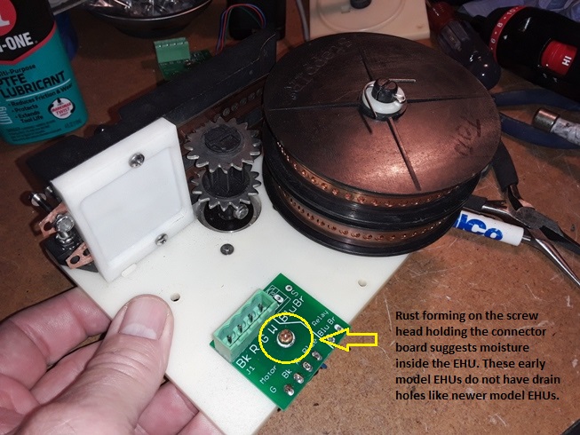 Connector board screw showing signs of rust
November 8,2020 (Sunday)
I took both EHUs outside on my back porch. One at a time I mounted each EHU on my test work bench and put the fiberglass poles on and ran the tapes out and back in several times. Both EHUs tested good. I then put a small amount of clear silicone sealant over all the screw heads on the top side of each EHU to prevent moisture from getting inside from the screw holes (thanks to Bill, K9HZ, & Dave NR1DX for their input on this).
 A dab of clear silicone was applied around the top of the screw heads
November 12, 2020 (Thursday)
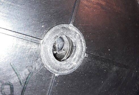
After considerable thought, I came up with a plan to add drain holes to the older gray EHU shells. Since I had a new-style black EHU shell (the one I bought from my friend), I used it as a guide. The drain hole is located on the bottom cover. On the inside of the cover is a 3/4″ indentation with a screen. In the center of the 3/4″ hole is the actual hole that goes to the outside. That hole measures 7/32″.
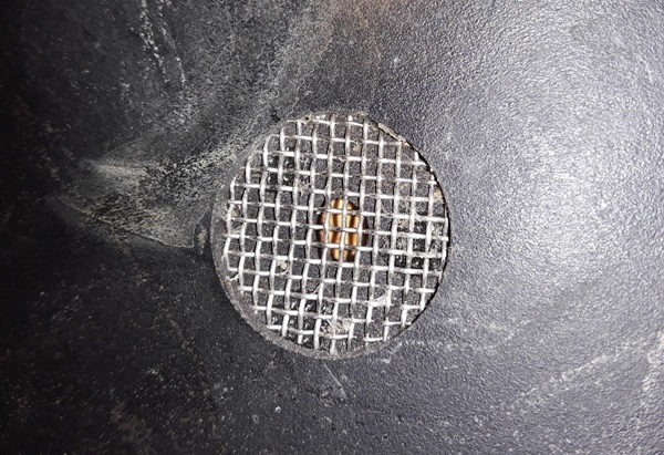 Drain hole in new-style black EHU cover as seen from the inside
I had a spare cover for an old style gray EHU to test with just in case I screwed up. I put the new style cover on top of the old style cover and made a mark where the center of the hole would go.
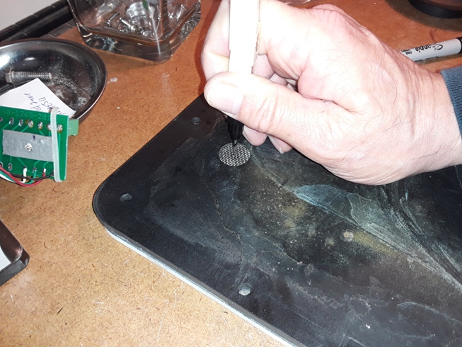 Marking the center of the drain hole using the new style cover as a guide
It occurred to me that others might also want to add drain holes to their older style EHU covers so I measured the location of the hole on the INSIDE of the cover. It was 3″ from the left side edge and nearly 2″ from the top edge (actual measurement was 1 15/16″ which is close enough to 2″ for this job).
It should be noted that the drain hole is located where the tapes go into the EST (element support tube) inside the EHU. The EST is the small tube with slits where the copper tapes go through to travel into the fiberglass poles. Also, the old style covers have a small inset indentation in the cover already. This inset indentation is to allow clearance for the top of the spool shaft. It can be seen in the first photo here. The drain hole goes on the opposite end of the cover from the inset for the spool shaft.

I then used a 3/4″ Forstner bit and drill press to drill the indentation (thanks to Kriss, KA1GJU, for this suggestion). It made a perfect inset in the cover.
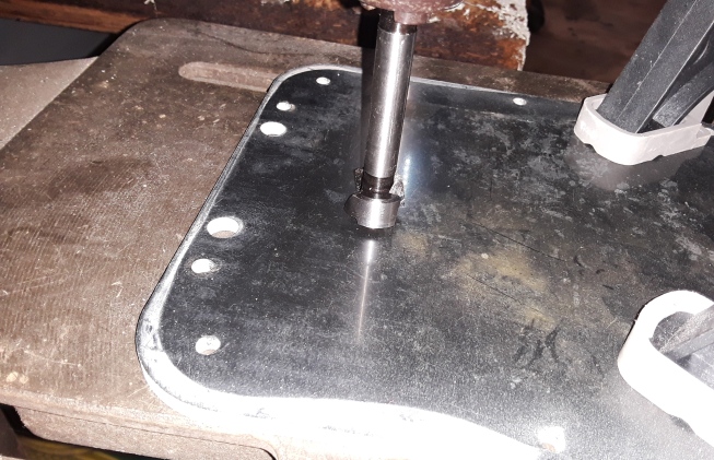 Drilling the inset for the new drain hole with a 3/4″ Forstner bit
A 7/32″ hole was then drilled the rest of the way through to the outside.
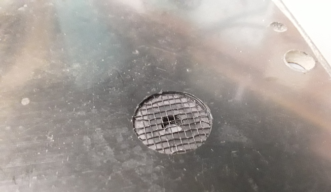
A screen was needed to keep bugs out. I found a small piece of screen material in my SteppIR spare parts box so perhaps I had this idea before. I used a penny as a guide to cut the screen with scissors since a penny is 3/4″ in diameter. This made a nice 3/4″ diameter screen.
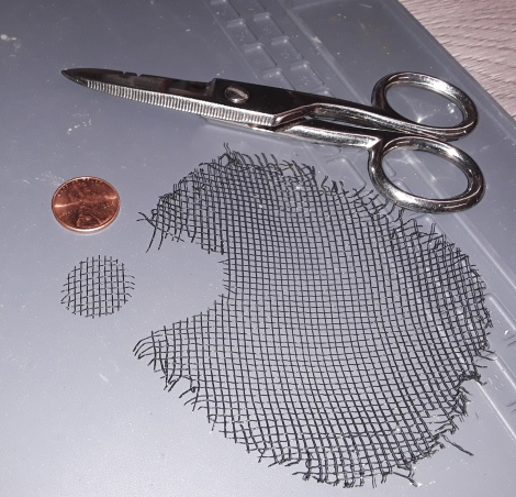 A penny is used as a guide to cutting the screen
I put the screen into the indentation and secured it with three small drops of super glue. I was pleased with the result so I did the same for the actual covers to the EHUs.
 New drain hole in old-style EHU
After the glue dried I installed the covers on the EHUs. They were now ready to be reinstalled back onto the boom.
November 15, 2020 (Sunday)
I brought the boom vertical alongside the tower and installed the reflector EHU and fiberglass poles. I also ran the control cable to the junction box.
November 18, 2020 (Wednesday)
I rotated the boom 180 degrees and installed the director EHU and fiberglass poles. I ran the control cables to the junction box. I didn’t connect the control cables just yet because it was dark. I will need to put the antenna in its normal position in order to have comfortable access to the junction box.
November 29, 2020 (Thursday)
I put the antenna back to its normal position and connected the control cables for the director and reflector in the junction box on the boom, then sealed the junction box.
November 21, 2020 (Saturday)
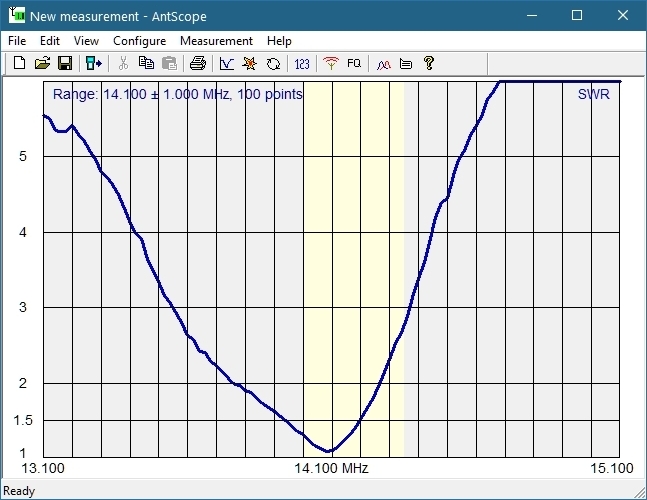
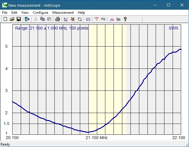
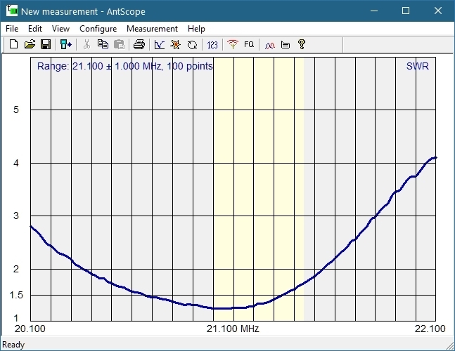
I reconnected the connector box at the base of the tower and made resistance checks of the motors – they were all good. I connected the SDA-100 controller and tested the antenna using a RigExpert antenna analyzer. Below are SWR graphs for 20, 15 & 10 meters both Normal and 180 mode (I rarely, if ever, use Bi-directional mode) . I am very happy with the results. The next step is to re-install my Cushcraft D40 rotatable dipole back on this tower. Before I had it too close to the SteppIR and it detuned the yagi. But I have a plan. More work to do. I hope to have all this working by the FT Roundup in December. We’ll see.
 20 Meters Normal mode
 20 Meters 180 mode
 15 Meters Normal mode
 15 Meters 180 mode
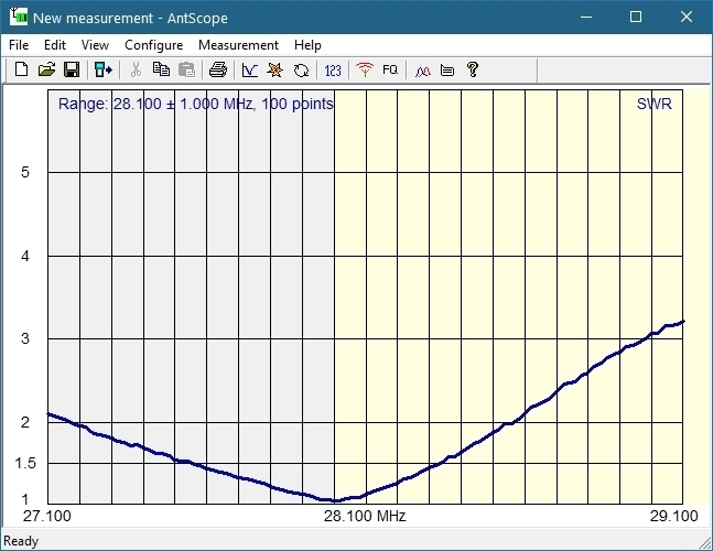 10 Meters Normal mode
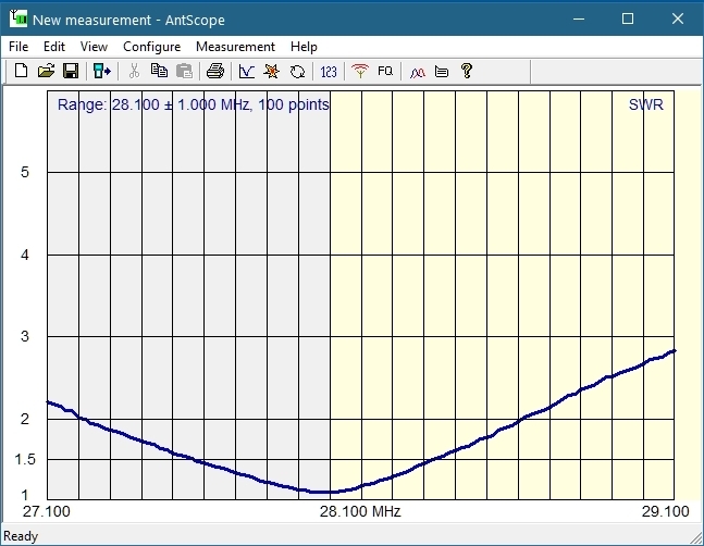 10 Meters 180 mode